
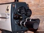
- typische historische Kamera

Zum Auffrischen und Erinnern . . . .
. . . sind diese Seiten hier gedacht, denn viele wissen nicht mehr oder noch nicht, wie es damals angefangen hat und wie das wirklich funktioniert mit dem Fernsehen, den Kameras, den Videorecordern, den Tonband- und den Magnetband- geräten aus alter Zeit. Viele Bilder können Sie durch Anklicken vergrößern.
Der Prospekt der LDK 3 vermutlich aus 1966 (in Englisch)
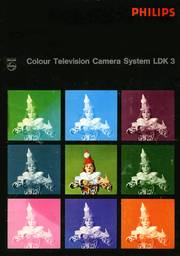
- Bunt ist der Clown ? Ob das etwas zu bedeuten hatte ?

Hier bilden wir den 28 seitigen Prospekt der Philips LDK3 Kamera ab, so gut es geht. Nicht alle Bilder sind enthalten, vor allem absolut belanglose und dann "wenig" hübsche Mädels aus unserem Nachbarland werden Sie nicht vermissen.
INTRODUCTION
The Philips LDK 3 is a third-generation Plumbicon Colour Camera for studio and outside broadcast use.
It represents a major advance in camera design, based on many years of successful experience with previous versions of three-tube Plumbicon colour cameras.
The latest colour television techniques and modular system lay-out have been employed to ensure high stability, reliability, and flexibility in operation.
FEATURES
- Three-tube camera with integrated "contours-from-green" principle for true colour and lifelike sharpness.
- Separate-mesh Plumbicon tubes for better overall resolution and excellent high-light handling.
- More efficient prismatic colour beam-splitting system and linear matrixing for optimum colorimetric response.
- Utmost flexibility in camera optics.
- Diascope lens attachment projects test pattern directly into camera for setting-up.
- Dynamic focusing for better overall picture sharpness.
- Modular type CCU in three separate sub-assemblies for high operational flexibility.
- Integral encoder and colour bar generator for "vector-scope-less" encoder adjustment
- Built-in test sawtooth and bridging facility for short video lining-up time.
- All-silicon circuitry for exceptional stability and "hands off" operation.
- Outstanding mechanical precision and rigidity.
- Full remote control facilities.
-
MECHANICAL LAY-OUT


Similar to the previous models, the camera is housed in a strong construction of aluminium alloy castings.
Hinged side-covers permit access to the interior. Electronic circuits are mounted on plug-in printed wiring boards, and the view-finder can be hinged out for easy access and servicing.
OPTICAL SYSTEM
Its precision lens-mounting allows the application of optical systems and drive systems using the latest techniques.
The wide range of high-quality zoom lenses available from the leading lens manufacturers includes fully servo-controlled lenses, as well as lenses with manually-controlled focus and zoom and servo-controlled iris.
The majority of these lenses accept range extenders. Zoom and focus demand units can be attached to the panhandles, the iris being controlled from the CCU or any remote position.
The servo amplifiers are located either in the camera or in the lens package, depending on the type of lens employed. Two independent motor-driven filter wheels are provided between lens and colour beam-splitter, one for colour-correcting filters and one for neutral density filters.
Selected from the CCU or any remote position, these filters serve for an instant matching of the camera to sudden changes in colour temperature or light input, such as are liable to occur in outside broadcast operation.
The colour beam-splitting system is the well-known prism-block with its two internal reflections per channel. It consists of three small glass prisms cemented together in such a way that the dichroic reflecting layers are fully protected.
The introduction of linear matrixing allowed the use of a more efficient colour beam-splitting prism.
PLUMBICON TUBES AND YOKE ASSEMBLIES


The XQ 1020 separate-mesh Plumbicon tube, the gun design of which is based on a 2-Watt cathode, allows for an increased beam-current.
The separate-mesh construction provides an extra parameter to control perpendicular beam-landing and also avoids picture distortion ("screw") related to over-beam conditions.
The result is an improved overall resolution, and a considerably extended linear transfer characteristic, so that excessive highlights can be handled without severe loss in resolution. In the red channel, the XQ 1023 - extended- red-sensitive Plumbicon - can be used.
The noise figure in this channel will then be improved by approx. 6 dB. Since red is 30 % of the luminance signal, the overall signal-to-noise ratio is improved approx. by 2 dB. E.R.S. (extended-red-sensitive) tubes allow reproduction of colours which contain large amounts of red, such as magenta. (See "Relative response" curve).
The deflection systems determining the registration of the three colour images are carefully selected for matched triplets. The deflection and focusing assemblies are efficiently screened by mu-metal cans to eliminate the influence of external magnetic fields on the registration accuracy, which could reduce overall performance.
The coil assemblies are framed in precisely machined castings, with accurate adjustments for optical focusing and picture rotation.
The complete deflection units are fixed into position on factory-aligned base plates by means of dove-tail arrangements with spring-loaded locking pawl.
ELECTRONICS
Apart from the signal amplifiers, the camera electronics comprise the following circuits:
-
- horizontal time base and blanking generator
- dynamic focusing
- internal test signal generator
- scan failure protection
- regulated power supply
- signalling
- intercom amplifier
- servo amplifier for the lens drive system (with certain types of lens).
-


Great care has been taken to stabilize the electronic circuitry, so that mains voltage and ambient temperature variations can be coped with, and the effects due to temperature variations of long camera cable connections do not influence camera performance. Apart from some pre-sets, the camera does not contain any setting-up controls, so that the complete lining-up of the camera chain can be carried out by one man from the CCU location.
The camera employs dynamic focusing to improve sharpness in the picture corners. For this purpose, parabolic signals of line and field frequency are added to the electrostatic focusing voltage of each pick-up tube. The calibrated sawtooth test signal in the camera can be switched at the CCU to the input of each camera amplifier to facilitate the setting of the complete video processing channels, and for checking the operational condition of the camera tubes.
A protection circuit in the camera switches the chain to "stand-by" position in the event of any horizontal or vertical scan failure. The electronic view-finder, a self-contained black-and-white picture monitor, with a 7-inch rectangular picture tube which has a bonded neutral density face-plate, can be hinged out of the camera housing for easy access.
The view-finder, which has a 16 kV HT supply, provides brilliant sharply-focused pictures.
Any combination of either R, G, B or Y, G, EXT video signals can be selected for display on the view-finder by means of an internal pre-set switch and three external push-buttons. The signals displayed are compensated in the CCU for cable lengths up to 300 metres.
The camera electronics incorporate an additional compensation for cable lengths up to 1000 metres. The "on-air" cueing system consists of an illuminated ring surrounding the lens inside the ray-shade, two lamps at the camera rear, one of which is located inside the view-finder window, and a top light screened at the front.
Inside the view-finder window is also located a "call" lamp, which can be flashed by the CCU-operator. Similar flashing light signals at the CCU can be reproduced by a momentary push-button at the camera rear.
Talk-back facilities are provided on the equipment for communication between camera, CCU and production room. The camera contains two parallel jacks for intercom headphones and a volume control. A separate socket is provided at the camera for special audio input.
An elapsed time meter at the camera indicates the operational hours of the camera tubes.
The camera chain (= der Kamera Zug) has been standardised on a single camera cable, Felten & Guilleaume type 756-1, to a maximum length of 1000 metres. No loss of performance will occur for cable lengths up to 600 metres and only minor specification data changing for cable lengths up to 1000 metres.
Other types of camera cable may also be applied; the maximum length will then depend on the particular type of cable used.
The Camera Control Unit
OVERVIEW


The various circuits are divided into functional sections, mounted in small modules, featuring a high degree of operational flexibility. The CCU has been split up into three separate sub-assemblies: the Electronics Unit, Local Control Unit and Power Supply Unit, which are linked by cables at the rear.
These sub-assemblies can be accommodated either in a standard 19-inch rack or in three separate 19-inch cabinets. In the latter case, the maximum cable length between the Electronics Unit and the Local Control Unit is 100 metres, and that between the Electronics Unit and the Power Supply Unit is 10 metres.
THE ELECTRONICS UNIT
The circuitry of this unit has been divided into functional sections and arranged in small modules of two sizes: the single module, one-twelfth of a 19-inch rack width; and the double module, one-sixth of this width. These modules, which are arranged in two rows in the unit, contain the circuitry for: video processing, including contour enhancement, pulse generation and timing, vertical scanning, focusing and beam alignment, picture switching, test signal generation, communication, signalling and remote control.
The Electronics Unit includes an encoder in accordance with the PAL or NTSC standard, and a colour bar generator for either the CCIR or EIA scanning system. The delay module of the contour extractor is also available in two versions, for the CCIR and EIA system respectively.
The unit also has two spare locations lodging module extenders. Advanced video processing techniques have been employed to ensure outstanding precision and stability of performance. The processing channels, therefore, include the following stages:
- cable length compensation (for a camera cable length up to 1000 metres)
- spurious pulse cancellation
- green tilt correction (green camera channel only)
- master gain switching
- colour balance switching (or painting)
- white clipping
- automatic black level control
- horizontal and vertical contour enhancement
- linear-matrixing for negative lobe compensation
- horizontal aperture correction (also usable as notch filter for noise reduction around the sub-carrier frequency)
- white limiting (adjustable to "sharp" and "soft" operation)
- adjustable gamma correction
-
LINEAR MATRIXING


This newly introduced circuit deserves additional comment. It is common knowledge that, for exact colour reproduction, the spectral analysis curves of the three colour channels should include negative lobes. These negative lobes, however, cannot be obtained by the colour-splitting system, or from the camera tubes.
This inadequacy can be largely compensated for by electronic means. This possibility has been known for a long time, but it only became practicable after the introduction of the Plumbicon tube, with its linear transfer characteristic.
The choice of the matrix coefficients depends on which colour areas should be particularly favoured. For this purpose, we developed a computer programme, with the aid of which the influence of different colour-splitting system characteristics, and their tolerances, was studied.
With this programme, we calculated the colour point co-ordinates of twenty-five important, highly- or less-highly saturated natural pigments, taking into account the characteristic curves of both the colour-splitting prism itself and the new phosphors used in the European shadow mask tube. This resulted in increased light currents at the green and blue Plumbicon tube, and at the same time improved colour rendition.
The increased light currents allow a gain in signal-to-noise ratio, and remarkably little "blue lag" The resultant overall camera spectral analysis, and colour reproduction obtained are shown in the illustration. (Note: the biggest colour reproduction is 7 j.n.d. (= just noticeable difference)
FURTHER DETAILS
The processing amplifier channels put out 5 sets of R, G, B gamma corrected signals (0.72 V into 75 Ohm) for monitoring, encoding and external use, as well as 1 set of R, G, B non-gamma-corrected signals for video testing. Either a saw-tooth signal from the test signal generator in the CCU, or an external test signal, can be switched to the video processing channels.
The remote control module is equipped with a meter and selector for monitoring all the power supply voltages, and with tally lights for power supply and scan failure indications. The camera chain is provided with a standard intercom system, but other systems can be employed, if required. The waveform monitor switch module provides a NAM (non-additive-mixed) signal, built-up from the largest amplitude and the lowest black-level information given by the red, green and blue video signals. This signal can be used for "simple" waveform control systems, automatic exposure control circuits, or "centralised camera matching".
THE LOCAL CONTROL UNIT


This unit consists of a pull-out drawer with operational controls at the front panel and setting-up controls at the top panel.
The front panel controls are for: iris, master gain, master black-level, camera off/stand-by/operation, colour bar on, local/remote control, colour correcting and neutral density filter selection, camera signal monitoring (R, -G, G, B, Y), internal and external test signal selection, power supply and scan failure indication, and talk-back control.
The negative green signal can be selected for display on the picture monitor, to facilitate an accurate registration setting. The top panel controls are for: tube-setting, registration, individual gain and black-level, gamma selection, painting, and bridging.
The top panel can be tipped for easy access to the interior of the drawer. The Local Control Unit also accommo-dates the Colour Waveform Monitor, type LDK 4910/00, a self-contained unit with 5-inch rectangular picture tube.
This waveform monitor displays the oscillograms of the three colour signals side by side or superimposed, separately or in any combination, and in line or field sequence. For special checks, the oscillograms can be spread over the entire width of the screen.
The waveform monitor has inputs for the following signals: R, G, B camera signals (input "A"); R, G, B camera signals (input "B"); coded composite colour signal (input "C"); and a reference signal for camera matching (input "G ref").
It also has a service probe input with switchable attenuator at the front panel, for monitoring the various signals at the test points of the modules.

OPERATIONAL CONTROL PANEL
Earlier mention was made of the remote control facilities. For remote "hands off" operation, the camera can be controlled by an operational control panel that carries only those controls necessary for programme operation, such as iris, master black, R, G, B painting for white and black. Painting control can be either by joysticks or individual potentiometers. In both versions there is a re-set possibility to restore the original colour balance.
THE POWER SUPPLY UNIT

The regulated power supply circuitry is divided between six double modules arranged in one row in the upper part of this unit, the lower part of which can accommodate the optional ventilator section, type LDK 4976/00. The voltage supplies for the video and scanning circuits have been separated to minimize interference.
All power supplies for the camera are automatically adapted to the various lengths of camera cable used. The mains voltage for the camera view-finder and the lens drive system are stabilised against fluctuations by means of a regulating circuit with motor-driven variable transformer.

BLACK/WHITE PICTURE MONITOR
A 14-inch all solid state picture monitor - type LDH 2151 - has been specially designed to match with the high degree of the colour camera channel.
The monitor can be delivered in cabinet or 19-inch rack mounting versions, depending on the CCU housing used - 3 cabinets or a 19-inch rack.
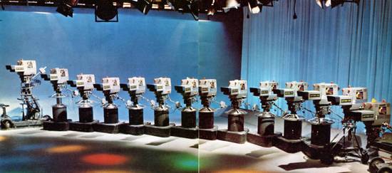
- Typisches Promotion Foto wie bei fast allen Herstellern, auch bei den RCA Leuten.

TECHNICAL DATA - COLOUR CAMERA CHAIN LDK3


Systems
CCIR 625-lines, 50 fields/s, 2 : 1 interlaced
or
EIA 525-lines, 60 fields/s, 2 : 1 interlaced
Power supply
Adjustable for 110/117 V or 220/234 V operation. 50—60 Hz, single phase.
Mains voltage variations of ± 5 % do not affect performance data specified.
Power consumption
Camera chain without lens servo system and waveform monitor: 300 VA.
Waveform monitor, type LDK4910/00: 60 VA.
Input signals
1. comp. blanking signal (B)
2. comp. sync signal (S) Both 0.75 to 4 Vpp negative going, across 75 Ohm, on loop-through sockets).
3. subcarrier signal (SC), 0.5 to 4 Vpp across 75 Ohm (loop-through sockets.
4a. external burst-gate pulses (bg), 0.5 to 4 Vpp across 75 Ohm (loop-through sockets). Internal burst-gate pulses are provided as well.
4b. "Kenn Impuls" signal (KP), 1 to 4 Vpp across 75 Ohm (loop-through sockets). For PAL encoding system only.
5. external test signal (EXT ENC), nominal 0.7 Vpp across 75 Ohm. A vertical interval test signal can also be applied at this input.
supplementary:
6. test signal (VB, monochrome saw-tooth or grid-pattern), + 0.7 Vpp across 75 Ohm (loop-through sockets), for lining-up the video processing channels.
7. external picture signal (VB, monochrome), + 0.7 Vpp across 75 Ohm, as over-lay signal on the picture monitor and/or camera view-finder. 8 external picture signal (VB, mono-chrome), + 0.7 Vpp across 75 Ohm (loop-through sockets), as over-rule signal on the picture monitor and/or camera view-finder.
Output signals
1. 2 x R, G, B gamma-corrected signals (VB), 0.7 Vpp across 75 Ohm, of which 1 set is intended for Colour Waveform Monitor LDK 4910/00.
2. 2 x R, G, B non-gamma-corrected signals (VB), 0.7 Vpp across 75 Ohm, to be used for video testing.
3. video signal (VBS), 0.7 Vpp across 75 Ohm, pre-selected for the picture monitor by switch on the Local Control Panel.
4. NAM (non-additive-mixed )signal, 0.7 Vpp across 75 Ohm, built-up from
largest amplitude and lowest black-level information from the R, G, B camera signals. To be used for "simple" control systems, automatic exposure control circuits, or "centralised camera matching".
5. 2 x composite colour signal (VBS), nominal 1 Vpp across 75 Ohm.
6. 1 x composite colour signal without sync (VB), nominal approx. 1 Vpp across 75 Ohm.
7. 2 x composite sync signal (S), 4 Vpp negative going, across 75 Ohm.
Scene illumination
1500 Lux (150 ft. cd.) for a signal-to-noise ratio > 40 dB in the Y-signal from the encoder at a signal level of 0.7 Vpp; with a reflection factor of the scene 0.6; with a signal current of 225 nano-Amp. in Green; lens iris set to f/4; master gain set to 0 dB; level-dependent aperture correction set to 6 dB at 5 MHz: gamma correction set to 0.6;
5 MHz signal bandpass; with contour enhancement operating at 60 % of maximum boost.
250 Lux (25 ft. cd.) for just acceptable pictures; with the lens iris set to f/2.2.
Resolution
With aperture correction, 100% modulation depth can be obtained at 5 MHz in each video channel.
Registration accuracy Deviations of Red or Blue in any direction with respect to Green
In area I, being the ellipse in the centre of the scanned picture with axes 0.9 of picture height and width, deviations will be no more than the distance equal to a horizontal scanning time of 40 nanosec.
In area II, being that part of the scanned picture outside area I but within a circle having a diameter equal to the picture width, deviations will be no more than 80 nanosec.
In area III, being that part of the scanned picture outside area II, deviations will be no more than 120 nanosec.
Registration drift
Deviations of Red or Blue in any direction with respect to Green
A. Variations of the ambient temperature of the camera of no more than ± 10°C from the temperature during registration setting (within the range of —10 to +45°C) will not cause mutual picture shifts larger than 50 nanosec.
B. External magnetic fields, not exceeding a field strength of 1 Gauss, will not cause additional registration errors of more than 25 nanosec within area I when the camera is moved or turned in any direction.
C. Mechanical shocks, such as occur during normal camera operation, will not have any influence on the picture registration.
Picture geometry
Maximum horizontal and vertical geometric distortion is 0.5 % of the picture height within area I (see colour registration). In the remaining picture area, maximum distortion is 1 % of the picture height.
Signal-to-noise ratio
Measured at a signal current of 300 nanoAmp.; without aperture correction, contour enhancement, and gamma correction. Within a video bandwidth of 5 MHz and measured at 40 % of peak white, the signal-to-noise ratio will be better than 45 dB, in each channel.
Contrast range
Each video channel can handle a contrast range of up to 60 : 1.
Gain control
Master selector for —6 dB; 0 dB; and + 6dB; individual control for ± 3 dB in each channel.
Painting control
± 2 dB in Red and Blue (before gamma correction).
Frequency amplitude response for processing amplifiers
Flat to within ± 0.5 dB at up to 5 MHz, —3 dB at 7 MHz, for each video channel, with minimum aperture correction.
Low frequency response
Tilt ^ 0.25 %/ms.
Aperture correction
In each channel, preset for amplitude boosting of maximum + 10dB at 5 MHz, and preset for amplitude threshold beyond which correction starts, adjustable between 0 and
100 % of white level. This circuit can be switched to the function of notch filter for noise reduction between 4 and 5 MHz.
Gamma correction
3-step selector for: linear operation, gamma = 0.35 to 0.6 (with preset adjustment),
gamma = 0.6 to 1 (with preset adjustment).
Gamma tracking at peak white level will be ^ 0.5 %, and near black level ^ 0.25 %, with respect to the gamma curve in the green channel.
Black-level adjustment
Master control for adjustment between —40 % and +50 % of the nominal white level.
Individual control in each channel for adjustment between —15% and + 15 % of the nominal white level. Automatic black-level compensation is provided in each video channel to minimize black-level shift due to optical flare.
Contour enhancement
Controls:
"S-correction" for minimum noise.
"Zero balance".
Preset adjustments:
for "H-V balance" (balance between horizontal and vertical contours).
for Hor. and Vert, contour symmetry. Amount of contour enhancement'
variable up to 0.7 Vpp for a pulse with a risetime of 100 nanos.
Camera cable
Standard camera cable is Felten & Guilleaume, type 756-1.
Minimum length 50 metres; maximum permissible length 1000 metres. Switchable compensation circuits are incorporated in the CCU for the above-mentioned single camera cable to a maximum length of 1000 metres.
Magnetic interference
No loss of performance in fields of up to 1 Gauss.
Acoustical noise
The acoustical noise level generated by lens controls and lens driving mechanisms will not exceed 30 dB at any position outside a 1 metre radius from the camera head.
Warming-up period
For the performance data specified, a warming-up period of 30 minutes should be taken into account. After a warming-up period of 2 minutes, excellent colour registration will be obtained.
Permissible ambient temperature
No change in performance data will occur at ambient temperature variations of ± 10°C with respect to the temperature during the line-up procedure, within a range of —10 to + 45°C.
Dimensions
See dimensioned sketches.
Weight
Camera without lens, servo amplifier or power supply unit: 42 kg.
Camera with zoom lens EL 8682/01, Angenieux 10x18.11, and complete servo control equipment: 75 kg.
CCU (Electronics Unit) in cabinet, complete with encoder and colour bar generator: 34 kg.
Local Control Unit, without waveform monitor: 16 kg (with waveform monitor 36 kg).
Power Supply Unit, without ventilator unit: 29 kg.
Tech Daten des Suchers

Frequency response
flat to 5 MHz ± 0.2 dB, —3 dB at 7 MHz.
Peaking at 5 MHz approximately + 7.5 dB.
Differential gain less than 5 % at 30 Vpp control voltage.
Resolution
better than 500 lines at a brightness of 250 ft. Lambert.
Geometry
within a circle having a diameter equal to the picture height: better than 1 % outside this circle: better than 2 %.
Picture tube
type: M 17-16W.
high tension: 16 kV.
picture size: 120x90 mm (diagonal
7 inch).
Maximum brightness
300 ft. Lambert.
Sind Sie zufrieden ? Hat es gereicht ?
Die Frage stellt sich, wer hat das je gelesen von den wenigen potentiellen Kunden. Diese waren zu jener Zeit unter solchem (Zeit-) Druck, daß sie jede Kamera, die nur irgendwie PAL und bunt aufgenommen hätte, gekauft hätten bzw. hatten. Die Macken merkten sie ja erst, wenn die LDK3 Kameras im Studio standen und die Bild-Meßtechniker sagten, das mit der Wärme-Empfindlichkeit ist so und das können wir nicht ändern.
.