
Bei den Profis dauerte es etwas länger mit den 3 CCDs
Die SONY Mavica Consumer- Chip-Kamera von 1981 war (nur) ein digitaler Fotoapparat. Bei den Filmleuten dauerte es etwas länger, bis der CCD-Chip so schnell war, daß damit Videos aufgenommen werden konnten. Anfänglich konnte diese frühe Video-Technik dem Super-8- und 16mm- Film qualitativ das Wasser nicht reichen.
Fatal getäuscht hatten sich die Film-Verfechter jedoch, was die Geschwindigkeit der japanischen Entwickler anging. Die konnten fast zaubern und die ganzen europäischen und auch die japanischen Hersteller von Filmkameras hatte es dann regelrecht kalt erwischt.
Es ging auf einmal ganz ganz schnell und der konventionelle "Film" war in wenigen Monaten out. So schnell hatte es nur wenige Wechsel oder Innovations-Sprünge in der Medien-Technik gegeben. Bei den Film-Profis dauerte es etwas länger und das ist die Geschichte der 3-Chip CCD Kameras auf professionellem Niveau.
Ein Artikel in der "Broadcast Engineering" April 1984"
Auf der jährlichen NAB Messe + Ausstellung wurde eine neue digitale Kamera auf CCD-Basis gezeigt, aber nicht von SONY oder CANON oder Ikegami, sondern von NEC.
.

.
NEC's new 3-chip CCD color camera
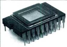
- Shown is one of the new NEC interline CCD chips used in the SP-3 video color camera. The registration of the three CCD imaging chips is permanently set in the factory.

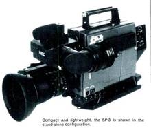
- Compact and lightweight, the SP-3 is shown in the stand-alone configuration.

Article by Masao Mitsui, director of engineering, NEC America, Elk Grove Village, IL.
Since they (die CCD Chips) were introduced in the late 1970s, video cameras using solid-state charge-coupled device (CCD) image sensors have generated a great deal of excitement in the broadcast industry.
With their mechanically locked registration, CCD cameras seemed particularly suitable for electronic-news-gathering, in which camera operators often are required to carry out tough ENG assignments in difficult circumstances with little or no time to set up.
Furthermore, CCD cameras promised to be considerably more rugged and reliable in operation, as well as lighter in weight and lower in power consumption, effectively easing the load of equipment ENG camera operators need carry with them.
Video cameras using solid-state CCD image sensors were expected to provide performance superior to that available from most conventional 2/3" pickup tubes. However, until recently, their use was confined mostly to industrial applications because their resolution was still inferior to that of Vidicon-type pickup tubes.
One of the problems that needed an immediate solution was the blooming phenomenon. The application of an overflow drain and barrier positioned beside the photosensitive area has made it possible to suppress the blooming phenomenon in CCD image sensors. However, this method was found to sacrifice photosensitivity and dynamic range.
.
- Anmerkung : Warum er (Masao Mitsui) das in einem absoluten Profi-Magazin alles nochmal wiederholt, das oben Ausgeführte war doch alles bekannt, ist nicht schlüssig.
.
A totally new interline CCD chip
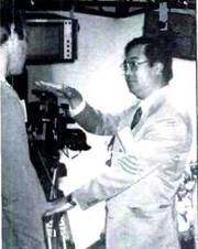
- The author (right), demonstrates the P-3 at the 1983 SMPTE Convention in ds Angeles.

To produce its first broadcast-quality CCD color camera, the SP-3, NEC has developed a totally new interline CCD chip, in which the contents of the multiple solid-state data registers are read out during the video picture's vertical interval.
- Anmerkung : Auch das stimmt nicht. Die Philips Ingenieure in Breda/Holland und die Kollegen von VALVO in Hamburg hatten um 1980 bereits den 1974 von RCA und später von Kodak (weiter-) entwickelten Chip auch wieder weiter entwickelt.
Die jeweiligen Entwicklungen in den firmeninternen Labors waren natürlich alle erstmal geheim. Die Geschichte dieser Entwicklung war Professor Michael Hausdörfers Domaine, die er mir authentisch vortrug.
The NEC interline CCD chip features a vertical overflow drain (VOD) positioned under, rather than beside, the photo diode, thus effectively increasing the cell area that can be used for photo electron generation and storage.
.
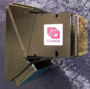
- der asymmetrische Strahlenteiler


Three of these interline VOD CCD image sensors are used in the SP-3 ENG color camera: two for the green channel alone, and one for the combined red/blue (RB) channels.
This dual green system, which can only be realized with a mechanically locked registration system, provides much higher resolution and sensitivity than can be obtained from a conventionally structured RGB system.
.
- Anmerkung : Hier wird es so ganz nebenbei und fast schon versteckt vorgestellt bzw. herausgestellt, es waren 2 Grün-CCDs und ein Rot-Blau CCD Chip --- und eben nicht 3 "Rot/Grün/Blau" Chips.
Zu dem Zeitpunkt (also vor 1983) hatte Philips bereits ein weltweites Patent auf den asymmentrischen Strahlenteiler. Und dieses (europäische) Patent mußte unbedingt "umrundet" werden, fast um jeden Preis. So war das japanische Denken damals.
Der Grund : Man mußte und muß heute noch beim Winkel der die Strahlen teilenden Prismen die Wellenlänge der Farbe Rot berücksichtigen und das konnte der symmetrische Strahlenteiller nur unzureichend. Also wurde in Japan versucht, dieses Patent zu umrunden.
.
The CCD image sensor
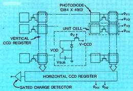
- Figure 1. Diagram of the VOD sensor.

Figure 1 shows the basic composition of the new interline CCD image sensor used in the SP-3 camera.
The sensor features a photoelectronic conversion system that consists of an array of 490(V) x 384(H) photo diodes, a transfer gate region (TG) controlled with a vertical transfer pulse, a buried channel vertical register (V-CCD), a horizontal register (H-CCD) and a gated charge detector for the output signal.
The photogenerated signal charges are transferred to the corresponding V-CCD through the TG (transfer gate) region during the vertical blanking period. There are two ways to accomplish the transfer: One is the field mode, which transfers all photogenerated signal charges at the field rate: and the second is the frame mode, which transfers half of the photogenerated signal charges during the first field period and the remaining half of the signal charges during the second field period.
The signal charges transferred to the V-CCD register subsequently are transferred to the horizontal register at the horizontal line rate and sent out to the output stage at the clock rate of the horizontal register.
A unit cell (indicated by the dotted line) consists of a photo diode, a half-stage V-CCD register and a VOD in which all of the photogenerated excess charges are drained into the substrate without flowing into the V-CCD.
By means of the vertical overflow drain, the cell area can now be used effectively for photo electron generation and storage, and increased photosensitivity and dynamic range can be maintained. In effect, this technique eliminates the blooming phenomenon.
A dual green image pickup system
In a conventional 3-tube elements camera, each of the elements is assigned to the RGB channels respectively. However, this method of one channel/element assignment is not effective if applied to the 3-chip CCD camera, yielding resolution problems, as well as signal aliasing problems, which are created by the use of solid-state chips as the image pickup elements.
Aliasing occurs in the CCD image sensor when the spatial freqency of image projected on the lage sensor in a given plane exceeds half the photo diode spacing in the image sensor on that plane.
To overcome these problems and to ovide the best balanced performance that can be achieved with current CCD chip pixel capacity 490(V) x 384(H) a dual green system was developed as the image pickup system for the SP-3 CCD camera.
.
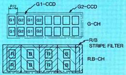
- Figure 2. Pixel arrangement.

As shown in Figure 2. two of the three CCD chips have been assigned the green channel, which requires a greater amount of light and a wider bandwidth, by means of a compensating arrangement of horizontal pixel interpolation.
The remaining chip was signed to the red/blue channels by means of a time sharing multiple process with an RB vertical strip filter.
.
Horizontal resolution of more than 500 TV lines.
Designed as a broadcast-quality stand-alone ENG camera, the SP-3 (shown here with Sony Betacam 172" recorder) offers universal interface to all videotape formats: 1/2" Beta or VHS, 3/4" U-matic, as well as 1/4" VCRs. Solid-state operational characteristics feature accurate and permanent registration that is free from geometric distortion.
The dual green system attempts to approximate the performance of the human eye as it perceives color, taking into account the following: The light value ratio of green to red/blue is approximately 1.5:2; and in the NTSC color system, the bandwidth ratio of the luminance channel to the chrominance channels is about 4:1.
Consequently, in spite of the limitations inherent in having only 384 pixels for the horizontal picture elements (per CCD chip), with the dual green system it was possible to obtain a horizontal resolution of more than 500 TV lines.
.
The optical system
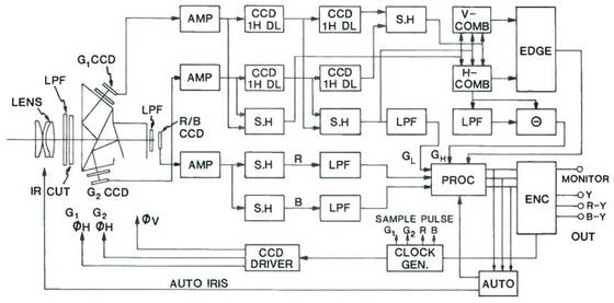
- Figure 3. SP-3 camera block diagram.

Refer to Figure 3 for the composition of the optical system employed to split the incoming light beam by prism. In front of the prism there is a series of filters: an ND filter (to help increase the camera's dynamic range), an IR cut filter and an optical low-pass filter (LPF).
The optical low-pass filter is used to minimize the aliasing problem, which is mainly caused by green light. In effect, the optical low-pass filter suppresses the spatial frequency of the image that causes aliasing on the CCD image sensor.
Because the dual green system is employed, the SP-3 camera uses a unique prism-optics block to split the incoming light beam into three beams: two greens for the Gl and G2 CCD image sensors and one magenta for the RB CCD image sensor.
One-half of all incoming green light is reflected at the first dichroic surface, and the remaining one-half of the green light is reflected at the second dichroic surface. Only magenta light passes straight through the prism without any reflection.
In this system, two green lights are reflected to precisely opposite directions against the light axis, thus minimizing achromatic effects that may occur when the image is out of focus and the iris is wide open.
Past the prism, another low-pass filter is inserted in the red/blue optical path to prevent aliasing and ghosting from the RB CCD image sensor. This is done because the bandwidth of the red or blue channel is effectively only one-quarter of the green channel bandwidth.
The CCD imaging chips are mounted directly on the optical assembly. The registration of the imaging chips is permanently set in the factory. No adjustment is ever needed.
.
Signal processing circuits
Combining the G signals (both) and splitting the RB (red-blue) signal - Refer to Figure 3 for a block diagram of the SP-3 camera. Because the horizontal shift registers of the CCD image sensors for Green1 and Green2 are driven by the two clock pulses (7.16MHz) with 180° phase shift, a 1H delayed signal and a 2H delayed signal for G1 and G2 can be obtained just through two 1H CCD-type delay lines without requiring a special delay line for phase matching respectively.
The non-delayed original signal, the 1H delayed signal and the 2H delayed signal for G1 and G2 are all combined, respectively, by three sample-and-hold (S.H) blocks, each consisting of two sample circuits and one hold circuit. Therefore, the data rate of the output signal from each of the sample-and-hold blocks is twice the rate of the output signal from each of the green CCD image sensors.
On the other hand, because the output signal from the red/blue CCD image sensor consists of alternating red and blue pictures at a rate of 7.16MHz, the red and blue signals can be easily split by using two sampling pulses (3.58MHz) with a 180° phase shift.
.
Image sharpener circuit
The camera features a 2H-line type image sharpener by means of a high performance CCD delay line (DL) which has a 400% dynamic range and a 62dB signal-to-noise ratio.
The CCD delay line and the green image sensors are driven in parallel with the same clock signal to maintain proper timing between the signal coming from the green CCD image sensors and the delayed signal through the CCD delay lines.
The output of the three sets of sample-and-hold blocks (non-delayed, 1H delayed and 2H delayed video) is then fed to a comb filter and image sharpener to peak the high frequency components of the green channel signal and to generate edge component signals. In this system, the high frequency component of the green channel is also used to feed the red and blue channel signals to enhance their frequency content.
Output signals -The camera provides the following output signals:
- • Y, R- Y and B - Y signal for component VTR;
- • composite video signal with SP-1 AD adapter; and
- • direct RGB output signal with SP-2AD adapter.
An NTSC composite signal is also available as monitor for the built-in VTR system in camera/recorder combinations.
.
Camera functions
The SP-3 camera incorporates auto and preset white balance, auto black balance, black stretch and auto iris.
The camera system
The CCD color camera is designed to be used as a broadcast-quality ENG stand-alone camera, as well as in camera/recorder combined systems using on-board component VTRs for E v G applications.
Enhancing the versatility of the camera, available camera adapter attachments interface to external conventional portable VTRs, as well as to RGB image processing systems as a special application.
The SP-1AD camera adapter attachment is used to generate composite video signal output for conventional VTR recording. The SP-2AD camera adapter provides direct RGB output for use as a document camera or for image processing applications.
Because the SP-1AD camera adapter contains genlock and I/Q type encoder modules, it will generate a burst signal and a color frame pulse that will meet the RS-170A standard, as well as NTSC color signal requirements.
Remote-control functions are available for gain, pedestal, iris, SC and horizontal phase control, etc.
Features
Compared with conventional 3-tube video cameras, the CCD camera offers several distinct advantages :
.
- Solid-state operational characteristics feature accurate and permanent registration that is totally free from geometric distortion. In normal operation, no CCD chip ever requires replacement or adjustment.
- Disturbances such as electrical circuit deviations or the earth's magnetism that can affect registration and cause geometric distortion in conventional magnetically deflected cameras are totally ignored by the SP-3 camera.
- Furthermore, the CCD camera is completely free from burn-in. sticking and comet-tail that may occur in conventional pickup tube cameras when ligh intensity objects are viewed. Even if you were to shoot directly at he sun, no damage would be incurred o the elements.
.
Artikel-Bemerkungen / Autoren-Ergänzungen zum obigen Text :
.
- As noted, under normal operation, the CCD chips of the SP-3 camera should never need replacement. If, for any reason, such replacement should ever become necessary, the camera should be returned to NEC for inspection and service. Although such service seems unlikely, BE explored the possibilities with NEC. The company said that individual chip replacement is possible. If the camera has been seriously mistreated, the entire optical block and all its CCDs can be replaced. In this worst-case situation, the cost would be approximately what you would expect for replacing the optics in a traditional tube-type camera. In any event, if your camera has been extensively damaged, you would probably want to replace it rather than service it.
- Aiming your expensive video camera at the sun, or at its reflection from a shiny surface, is not a recommended practice. However, according to NEC experts, such action, accidental or deliberate, does not have any apparent adverse effect on the immediate or long-term performance of the SP-3 camera. It is our understanding that NHK in Japan set up a CCD camera to tape an eclipse of the sun. A segment of the resulting tape was subsequently broadcast so that the public could view the event. BE is researching this work and will report details when they become available.
.
Editor's note:
.
- This article on the SP-3 CCD camera was provided courtesy of NEC America and excerpted from the NEC Synchronizer, Volume 2, No. 1, Winter 1984. A production version of the SP-3 camera was introduced at the SMPTE-1983/Los Angeles Convention, Oct. 30-Nov. 4, 1983. The camera is available now from NEC essentially from stock, for approximately $ 19.000 (without lens). For a quotation, contact the Broadcast Equipment Division from NEC America.
.
SP-3 Performance Specifications
| Color System | NTSC Color Signal |
| Pickup Image Devices | CCD Solid-State Image Sensors |
| uPD 3511 Green Channel | |
| uPD 3512 Red/Blue Channel | |
| Optical System | F 1.4 Prism Optics |
| Signal-to-Noise Ratio | More than 55 dB |
| Sensitivity | f/5.0 - 2000 Lux, 3200°K, 89.9% Reflectance |
| Resolution | Horizontal - More than 500 tv-lines (Linien) |
| Vertical - More than 350 tv-lines (Linien) | |
| Operating Temperature Range | -20°C to +45°C |
| Power Consumption | Approx. 12W |
| Dimensions (Camera Only) | 90mm (W) x 178mm (H) x 155mm (D) |
| Weight (Camera Only, with Viewfinder, less Lens) | Approx. 2.7kg (5.9 lbs.) |