
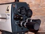
- typische historische Kamera

Zum Auffrischen und Erinnern . . . .
. . . sind diese Seiten hier gedacht, denn viele wissen nicht mehr oder noch nicht, wie es damals angefangen hat und wie das wirklich funktioniert mit dem Fernsehen, den Kameras, den Videorecordern, den Tonband- und den Magnetband- geräten aus alter Zeit. Viele Bilder können Sie durch Anklicken vergrößern.
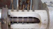
Der gesamte Kopfträger besteht aus 2 Teilen - dem Ton-Teil .....


Der Kopfträger-Bereiche (beide Kopfträger) sind normalerweise mit einer großen Haube oder Klappe angedeckt, um den Staub möglichst fern zu halten.
Der rechte feste Teil mit den 3 Audio-Tonköpfen ist (war) unproblematisch, außer, das es zu der Zeit ungewöhnlich war, auf ein 2" Band zwei winzige Ton-Spuren zu schreiben.
Diese 3-Kopf- Ton-Technik wurde durch einen ebenso großen (= hohen) fest montierten Löschkopf links vor der steckbaren Video-Kopfträger-Einhet ergänzt, mit dem das gesamte Band mit allen Informatiien komplett gelöscht wurde.
Bei den Audio-Tonköpfen war die Technik bereits ziemlich weit fortgeschritten und warum bei 38cm/s (39,5cm/s) nur schlechte Radioqualität möglich war, ist mir ein Rätsel geblieben. Die Innovation und die damals neu zu beherrschende Technik lag im nämlich Videobereich.
.
..... und dem Video-Kopfträger mit dem "Scanner" :


Es mußte für damalige Zeiten eine sehr große Menge an Daten auf das Band geschrieben werden. Das ging nur mit hoher absoluter (Kopf-) Geschwindigkeit imBezug auf das Magnetband und damals aus technischen Gründen nur quer zur Laufrichtung des 2" Bandes. Und da das Band nicht beliebig um ein kleines drehendes Kopfrad gewölbt werden konnte, wurden aus einem Magnetkopf dann 4 Köpfe pro Umdrehung des kopfrades. Das Fernsehbild wurde waagrecht in 4 Teile geteilt und mit den 4 Köpfen nacheinander auf je eine Spur geschrieben.
Den Anfang der Probleme beschrieb Chales Ginsburg in seinem Rückblick mit der unerwartet hohen Fliehkraft des wirklich kleinen Magnekopfes bei 15.000 "rounds per minute" (rpm).
War das Kopfrad auf volle Touren hochgelaufen, schossen viel zu oft diese kleinen Köpfe wie kleine Raketen aus dem Rad raus. Die damalige Mechanik konnte die doch enormen Fliehkräfte nicht vertragen. Daran hatten sie Monate geknobelt und experimentiert, wie man das hin bekomen könnte.
.
Die Signal-Übertragung aus dem rotierenden Kopfrad ....
- Ein RCA Schleifring-Foto

- Ein Ampex Schleifring-Foto

Das nächste Problem war die Übertragung der vier (kleinsten) Kopfströmchen aus dem Rotor in den Stator und zur Elektronik. Die ausgewählte Schleifringtechnik mußte auch diese 15.000 rpm aushalten und zwar über Stunden.
Deshalb hatten die fünf Messing-Schleifringe einen ganz kleinen Durchmesser. Damit war der Umfang (= Weg des Schleifers) recht kurz und die Wärmeentwicklung der Kohlekontakte war beherrschbar.
Diese Schwäche wurde nach unseren Unterlagen bei Ampex durch den sogenannten "rotierenden Übertrager" genial gelöst - soetwas kannte man bis dahin nicht, daß bei einem Übertager oder Transformater sich die beiden Wicklungen durchaus gegeneinander bewegen könnten.
Die Pegelverluste wurden durch spezielle direkt unter dem Kopfträger befindliche Vorverstärker ausgeglichen.
.


Das größte Probelm bei der Video- Signalübertragung war der Pegel
Bei der Aufnahme konnte man über entsprechende Verstärker einen recht hohen Signal-Pegel an die 4 Videoköpfe anlegen. Doch bei der Wiedergabe kam davon nicht mehr so viel zurück. Jetzt mußten die kleinsten Video-"Strömchen" deutlich verstärkt werden und das so nah an der Kopfträgereinheit wie nur wöglich.
.
Dazu wurde direkt unter der Kopfträgereinheit ein langer schlanker Verstärker-Einschub plaziert, der die Aufnahme- und Wiedergabe- Verstärker mit den Video-Transistoren (im MHz Bereich) enthielt, metallisch gut abgeschirmt und mechanisch richtig massiv, damit da nichts schief läuft.
.
Wenn wir heute da rein schaun, ist das die Technik aus den allerersten Anfängen der Transistortechnik.
In den ganzen Einschüben dieser TR 22 ist alles noch von Hand gelötet.
.
Die Präzision der beiden Kugellager


Bei der ganzen Quadruplex- Technik mit dieser hohen Rotationsgeschwindgkeit von ca. 15.000 U/min war ganz am Anfang das Problem der Spurführung bei diesen ganz ganz schmalen Video-Spuren ein dickes Problem.
Aus statischen Gründen der Fliehkräfte war der Kopfrad- Spindel-Motor bereits recht schlank und dafür recht lang und anfänglich waren die beiden Kugellager so weit wie möglich ganz außen plaziert.
Das reduzierte damals schon mal Verkantungsprobleme, wie wir sie von alten analogen Plattenspielern mit ganz kurzen Teller-Achsen her kennen. Doch auch die besten amerikansichen Präzisionskugellager hatten Schwächen, der Rotor vibrierte bei dieser Geschwindigkeit - schwer meßbar - brachte aber das (viergeteilte) Bild sichtbar aus dem Takt.
Außerdem verschlissen diese Kugellager nach zwei oder drei Kopfrad-Reparaturen alle 150 bis 230 Kopfstunden. (Hintergrund : nach ca. 150 bis 230 Stunden Laufzeit waren die vier Köpfe des Kopfrades abgeschliffen und damit unbrauchbar).
.
Kugellager waren nicht die langfristige Lösung

Bei der Lagerung von beweglichen Teilen in Elektromotoren und Generatoren (dort ist allermeist ein Rotor im Inneren des Stators) werden sogenannte Wälzlager oder Gleitlager verwendet. Bei extremen Gewichten wie bei Dampflokomotiven waren es allermeist ölgeschmierte Gleitlager, die wirklich kontinuierlich geschmiert werden mußten. Bei Wälz- = Kugel-Lagern wird eine Einmalfettung für die Lebensdauer des Lagers eingebracht.
Doch bei 15.000 rpm ist das Fett bald weg (geschleudert) und die Kugeln "tanzen" in den beiden Rillen bzw. in der Führung herum. Nicht nur, daß man das hörte, die Lager laufen nicht mehr rund. Bei einem normalen Motor ist das oft unproblematisch.
Doch bei dem Scanner sitzt das Kopfrad mit auf der Rotor-Achse und läuft auch nicht mehr "absolut rund". Und "relativ rund" reicht bei Video nicht.
.
So wurde aus dem "ball-bearing" ein "air-bearing"

Ich weiß nicht, ob das aus dem Flugzeugbau oder aus der Präzisions-Meßtechnik kam, jedenfalls haben sie bei Ampex einen Scanner mit Luftlagerung entwickelt. Die Rotor-Achse von Motor und Kopfrad dreht an beiden Enden auf einem Hochdruck-Luftposter.
Es gab bei uns die billigen Scherze, daß Lehrlinge ins Lager geschickt wurden, um sogenannte Siemens Lufthaken zu beschaffen und dann ausgelacht wurden. Hier ist wirklich eine Lagerung einer Motorachse mit zwei Luftlagern gelungen - und es war kein Scherz.
Natürlich wurde jetzt ein leistungsstarker Kompresser gebraucht, der die Luft-Kammern der beiden Lager bereits vor dem Beginn jeglicher Drehung unter Druck setzte. Größtes Problem war dabei, den Kompressor durfte man weder hören noch dessen Vibrationen auf das Recorder-Chassis übertragen.
Hierzu folgt eien Artikel aus der RCA Hauszeitschrift :
.
AIR BEARING HEADWHEEL PANELS FOR RCA TV TAPE RECORDERS - Vol. No. 773 - May, 1962

by FRANK M. JOHNSON Broadcast Equipment Engineering - Vol. No. 773 - May, 1962 - published by RADIO CORPORATION OF AMERICA - BROADCAST & COMMUNICATIONS PRODUCTS DIVISION, CAMDEN, N. J.

Introduction of air bearing headwheel panels for use with RCA TV Tape recorders is a major step in the steady improvement of this equipment.
Advantages made possible by floating the motor shaft and headwheel on a film of air are numerous. Use of air bearings leads to steadier pictures because of the elimination of a source of vibration. Longer life results because there is no metal-to-metal contact as the motor shaft revolves. Another result is superior Pixlock operation because of more uniform rotational drag characteristics of the air film.
The air bearing panels are available for use with all RCA TV Tape recorders. They may be used interchangeably with ball bearing panels by installing an air supply system kit. TRT-1B and TR-11 recorders can be modified to use these panels in about five man-hours. The new transistorized TR-22 recorder includes the air supply system as regular equipment.
Freedom from Vibration
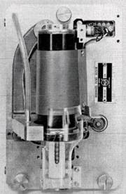
- FIG. 1. Air bearing headwheel panel - available for use with all RCA tv tape recorders.

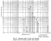
- FIG. 2. Vibration plots of both ball bearing panels and air bearing panels (see legend).

Probably the most important feature of air bearings for video use is their complete lack of vibration as compared to the characteristic spectrum of vibration of ball bearings.
In the vibration plot of a ball bearing, Fig. 2, noise components may extend from one hundred cycles per second to ten thousand cycles per second. The amplitude of the noise varies through the frequency range. Because of the metal-to-metal contact of the balls on their inner and outer races, there is always some vibration at many frequencies.
Ball bearings when judged acceptable with respect to vibration may produce picture jitter when the panel plays back its own recorded signal. This is a more severe test for picture jitter than playing back a standard or perfect tape, because the jittering signal is compounded as the vibration fault is first written on the tape and then read with the same fault.
The error is correspondingly doubled. This condition is compounded further if the headwheel is used to make additional copies of its recording.
.
The vibration plot of an air bearing (also shown on Fig. 2) has no detectable vibration except the shaft speed frequency, and this may be reduced in amplitude by counterbalancing.
The 360 cps frequency which is the electrical drive frequency of the 3-phase motor, the slip frequency of 120 cps (which is the difference between the drive frequency and the shaft speed), and the harmonics of these may show on the plot as vibrations.
These are drive vibrations and may be changed by changing the drive frequency should they cause picture unsteadiness.
Air Flow
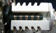
The air bearing video headwheel panel is supplied with one-half cubic foot of air per minute at a pressure of thirty-five pounds per square inch. This air enters each bearing through six central throttling orifices, as may be seen in Fig. 3, so that the shaft is held equidistant from each orifice by air pressure. If the shaft is pushed toward an orifice (thereby reducing both the clearance and How of air from the bearing at this point) the pressure against the shaft increases.
On the opposite side of the shaft, the air pressure is reduced due to increased clearance which allows the air to escape as the throttling orifice restrains the supply of air to this part of the bearing. This action is the centering influence which holds the shaft in the center of the bearing before it starts to rotate and also at full speed. A simple, sturdy design results which gives smooth operation and high reliability.
Long Life Design
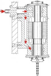
- FIG. 3. Cross-sectional diagram of air bearing panel. Air How is shown by white areas.

Another important feature of the air bearing is its unlimited life, provided it is supplied with clean, reasonably dry air. This is due to the complete flotation of the shaft, and the elimination of metal-to-metal contact. Ball bearings are classified as frictionless because the relative motion of the contacting metal is a rolling contact, and the area is a small oval less than the head of a pin. Yet grease is necessary to lubricate the rolling balls and to reduce their wear. The life of the ball bearing is limited by loading, speed, and the amount of grease which can be kept in contact with the balls.
The only part that wears in the air bearing is the lubricant, air. This means that the air bearing will have a life limited only by obstruction or supply failure. Should these occur the likelihood of repair is excellent due to the use of very hard materials which resist the abrasion of most dirt and are non galling.
It is obvious that ball bearings are performing creditably today, but they do have risk characteristics which are magnified as the life of the magnetic heads is increased. The continuing search for materials and designs to increase the life of the magnetic heads indicates that head wear life may be greatly extended and it is important that the bearing system does not detract from the magnetic head performance nor reduce its life span. Air bearings have been known to function continously for years and obviously meet this requirement.
Picture Improvements
Another characteristic of air bearings is shown to advantage when using the RCA Pix-lock system. This is an advanced servo system which synchronizes the output picture signal from the tape recorder with the local sync generator by comparing tape-produced horizontal sync pulses with the local signals.
Here the uniform drag of the air film reduces rotational vibration of the headwheel and results in consistent lock-in and superior picture stability.
The quadrature angles of the magnetic headwheels may be expected to show less deviation in the air bearing panel. This is because the bearing surfaces are never replaced nor do bearing elements rotate, as do balls, to cause changes in the center of rotation. The air bearing shaft is one large part, which is precisely round, and establishes the axis of rotation about which the heads rotate.
Air bearing assemblies are very rugged. They are not subject to damage by shocks or vibration such as might "brinell" the
ball bearings during shipment. Also, thermal effects of the motor shaft have not been evidenced. Air bearing motors run cooler than ball bearing motors, require less drive power than ball bearing motors.
Technological Advance
The air bearing video headwheel panel assembly offers considerable improvement in life, performance and overall economy of tv tape headwheels. It has been established as a major step from which greater improvements in performance and picture quality are possible. The basic simplicity of its design promises greater reliability and superior service to tv tape operations.
.
Die Pumpenmechanik im Bauch des Recorders

Wie im amerikanischen Text von 1962 ausführlich wiederholt, muß die Luft für die Luftlager des Scanners absolut sauber und trocken sein. Das sei für die eigentlich unendliche Lebensdauer der Lager ganz entscheident.
Die Luft für die Magnetköpfe und das Magnet-Band hingegen soll nicht trocken und nicht feucht, also ein Mittelding von beiden Zuständen sein, sonst klebt das Band an den Führungen.
Dashalb war die Aufstellung und Einrichtung in den unterschiedlichen Ländern kritisch. In den beiden ZDF Versionen wurde offensichtlich ganz schön rum-expierimentiert, wie und wo welche Luft be- oder entfeuchtet werden mußte.
.
.