

Welcome
to the Indigo-Service-CD - Rev 10: vom April 2011. (Grass Valley Germany GmbH 2011)
.
Safety Instructions
Before opening the INDIGO AV Mixer, unplug the power cable. Any instructions that require opening the equipment cover or enclosure are for use by qualified service personnel only. To reduce the risk of electric shock, do not perform any servicing other than contained in the manual unless you are qualified to do so.
.
Das Manual beschreibt nur den Austausch von Komponenten
Wie der Techniker herausfinden kann, welches Modul bzw. welche Komponente defekt ist und den Indigo am "Booten" hindert, ist nach wie vor nicht bekannt. Die Bescheibung der Lage der Testpunkte und der Signale auf den Boards wäre da sicher hilfreich.
.
Electrostatic sensitive devices on the p.c. board.

Observe the following precaution instructions for handling!
When opening the INDIGO AV Mixer, be aware of ESD-Protection after DIN 100 015-1. Make sure there is a potential equalization between the body, the device ground and the case ground by using a common ESD-wristlet.
Never remove or insert p.c. boards when the production switcher is switched on.
To prevent damages caused by static charging, please use antistatic packing, if you are sending boards to Grass Valley Germany.
.

Mounting Instructions (die Aus- und Einbau-Hilfen)
Wir lassen es hier bei der englischen Sprache. Wer sich hiermit beschäftigt, sollte sie verstehen.
- Bild 01

- Bild 02

- Bild 03

- Bild 04

- Bild 05

- Bild 06

- Bild 07

- Bild 08

- Bild 09

- Bild 10

RY4150 - Analog Audio Board
.
Exchanging Procedure
.
- Switch power off and disconnect cables.
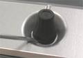
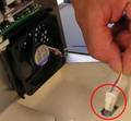
- Remove all soft knobs. Use a screwdriver to push upwards.
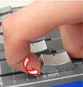
- Remove the 6 fader knobs and use your finger to push upwards.
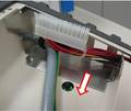
- After removing the fader knobs move the audio faders to the middle position.
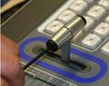
- Unscrew the screws on the right side of the fader grasp. Take the 2 metal pins off.
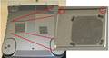
- Turn the whole switcher over and remove 2 screws on the fan door.
- Lift the fan door and loosen the cable from the fan.
- Loosen the 2 screws on the power supply door.
- Lift the power supply door and loosen the power connector.
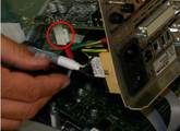
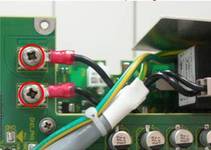
- Loosen the power connector on the other side of the power supply door (2 yellow-green and 1 black cable).
- Loosen the fan connector and remove it.
- Remove the cable holder.
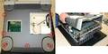
- Loosen the 7 screws on the underside of the unit. Turn the Indigo the right way around and carefully lift the case up.
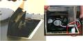
- The Flash Card door will come loose.
- Loosen the 8 screws on the RY4120.
- Lift the board package up and loosen the cable to the headphone connector.
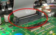
- Loosen the ribbon cable from the display and carefully lift the board package upwards.
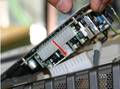
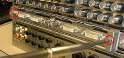
- Loosen the 2 screws on the back of the High Resolution Board and pull it out.
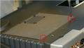
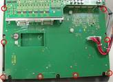
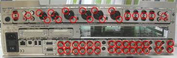
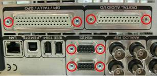
- Loosen the 19 screws and 28 BNC nuts on the back.
- Loosen the 8 hexagonal columns on the back.
. - At the Digital Audio I/O Connector are M3 threads.
- Loosen the 2 screws on the RY4120.
- Remove the metal part from the back.
- Turn the board package over.
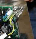
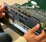
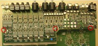
- Loosen the 3 screws and carefully lift the Analog Audio Board upwards.
- Remove the protection covering from the new Analog Audio Board.
- Carefully mount the new Analog Audio Board and fasten the 3 screws.
- Mount the back metal part and fasten the 19 screws, 28 BNC nuts and the 8 hexagonal columns.
- Connect the 2 cables of the Power Entry Module to RY4120 and fasten the 2 screws.
- Mount the High Resolution Board and fasten the 2 screws.
- Put the board package into the case and lift it up to reconnect the headphone cable and the ribbon cable to the display.
- Fasten the 8 screws on RY4120.
- Mount the underside of the case and fasten the 7 screws.
- Mount the cable holder.
- Mount the power supply door, connect the fan cable and all the power cables.
- Close the door and fasten the 2 screws.
- Mount the fan door and connect the fan cable.
- Close the door and fasten the 2 screws.
- Turn the whole switcher over.
- Mount the 2 pins onto the fader and fasten the screw.
- Mount the 6 fader knobs.
- Remount all the soft knobs.
.
- Bild 11

- Bild 12

- Bild 13

- Bild 14

.
- Hier stimmt die Demontage-Beschreibung nicht so ganz. Das analoge Audio Board bekommt man auch raus, wenn die Alu-Rückwand noch dran ist. Nur die Schrauben der ganzen XLR Reihe des Audio-Boards müssen raus.
.
- Bild 15

- Bild 16

- Bild 17

- Bild 18

.
- Wenn die Schrauben der analogen Buchsen alle draussen sind, kann man das gesamte Audio-Board nach dem Lösen der 3 dortigen Schrauben leicht anheben und heraus-ruckeln. Das ist wesentlich leichter als die hier beschriebene aufwendige Prozedur.
.
- Bild 19

- Bild 20

.
Die Ausbau-Beschreibungen der anderen Komponenten und Teile sind sehr ähnlich.
.
RY4130 - Digital Audio Board
.
Exchanging Procedure
.
- Switch power off and disconnect cables.
- Remove all soft knobs. Use a screwdriver to push upwards.
- Remove the 6 fader knobs and use your finger to push upwards.
- After removing the fader knobs move the audio faders to the middle position.
- Unscrew the screws on the right side of the fader grasp. Take the 2 metal pins off.
- Turn the whole switcher over and remove 2 screws on the fan door.
- Lift the fan door and loosen the cable from the fan.
- Loosen the 2 screws on the power supply door.
- Lift the power supply door and loosen the power connector.
- Loosen the power connector on the other side of the power supply door (2 yellow-green and 1 black cable).
- Loosen the fan connector and remove it.
- Remove the cable holder.
- Loosen the 7 screws on the underside of the unit. Turn the Indigo the right way around and carefully lift the case up.
- The Flash Card door will come loose
- Loosen the 8 screws on the RY4120.
- Lift the board package up and loosen the cable to the headphone connector.
- Loosen the ribbon cable from the display and carefully lift the board package upwards.
- Loosen the 2 screws on the back of the High Resolution Board and pull it out.
- Loosen the 19 screws and the 28 BNC nuts on the back.
- Loosen the 8 hexagonal columns on the back.
- At the Digital Audio I/O Connector are M3 Threads.
- Loosen the 2 screws on the RY4120.
- Remove the metal part from the back.
- Turn the board package over.
- Loosen the 3 screws and carefully lift the Analog Audio Board upwards.
- Loosen the single hexagonal column and the single screw on the Digital Audio Board.
- Carefully lift the Digital Audio Board upwards.
- Remove the protection covering from the new Digital Audio Board.
- Carefully mount the new Digital Audio Board and fasten the single screw and the single hexagonal column.
- Mount the Analog Audio Board carefully and fasten the 3 screws.
- Mount the back metal part and fasten the 19 screws, 28 BNC nuts and the 8 hexagonal columns.
- Connect the 2 cables of the Power Entry Module to RY4120 and fasten the 2 screws.
- Mount the High Resolution Board and fasten the 2 screws.
- Put the board package into the case and lift it up to reconnect the headphone cable and the ribbon cable to the display.
- Fasten the 8 screws on RY4120.
- Mount the underside of the case and fasten the 7 screws.
- Mount the cable holder.
- Mount the power supply door, connect the fan cable and all the power cables.
- Close the door and fasten the 2 screws.
- Mount the fan door and connect the fan cable.
- Close the door and fasten the 2 screws.
- Turn the whole switcher over.
- Mount the 2 pins onto the fader and fasten the screw.
- Mount the 6 fader knobs.
- Remount all soft knobs.
.
RC4116 - Audio Fader (die 6 Flachbahn-Steller)
Die mit Motorantrieb einstellbaren Flachbahn-Steller sind die eigentlich empfindlichen Komponenten, die auch sehr "leicht" konstruiert sind und bei heftiger belastung ausfallen könnten.
.
Exchanging Procedure
.
- Switch power off and disconnect cables.
- Remove all soft knobs. Use a screwdriver to push upwards.
- Remove the 6 fader knobs and use your finger to push upwards.
| After removing the fader knobs move the audio faders to the middle position. |
- Unscrew the screws on the right side of the fader grasp. Take the 2 metal pins off.
- Turn the whole switcher over and remove 2 screws on the fan door.
- Lift the fan door and loosen the cable from the fan.
- Loosen the 2 screws on the power supply door.
- Lift the power supply door and loosen the power connector.
- Loosen the power connector on the other side of the power supply door (2 yellow-green and 1 black cable).
- Loosen the fan connector and remove it.
- Remove the cable holder.
- Loosen the 7 screws on the underside of the unit. Turn the Indigo the right way around and carefully lift the case up.
| The Flash Card door will come loose. |
- Loosen the 8 screws on the RY4120.
- Lift the board package up and loosen the cable to the headphone connector.
- Loosen the ribbon cable from the display and carefully lift the board package upwards.
- Loosen the 14 screws and carefully lift the Switch Board upwards.
- Turn the RY4110 over and loosen the cables.
- Lift the Audio Fader out and put the new one in.
- Connect all cables to the RY4110.
- Carefully mount the Switch Board on the RY4120 and fasten the 14 screws.
- Put the board package into the case and lift it up to reconnect the headphone cable and the ribbon cable to the display.
- Fasten the 8 screws on RY4120.
- Mount the underside of the case and fasten the 7 screws.
- Mount the cable holder.
- Mount the power supply door, connect the fan cable and all the power cables.
- Close the door and fasten the 2 screws.
- Mount the fan door and connect the fan cable.
- Close the door and fasten the 2 screws.
- Turn the whole switcher over.
- Mount the 2 pins onto the fader and fasten the screw.
- Mount the 6 fader knobs.
- Remount all soft knobs.
.
RC4161 - Display cpl.
.
Exchanging Procedure
.
- Switch power off and disconnect cables.
- Remove all soft knobs. Use a screwdriver to push upwards.
- Remove the 6 fader knobs and use your finger to push upwards.
After removing the fader knobs move the audio faders to the middle position. |
- Unscrew the screws on the right side of the fader grasp. Take the 2 meta pins off.
- Turn the whole switcher over and remove 2 screws on the fan door.
- Lift the fan door and loosen the cable from the fan.
- Loosen the 2 screws on the power supply door.
- Lift the power supply door and loosen the power connector.
- Loosen the power connector on the other side of the power supply door (2 yellow-green and 1 black cable).
- Loose the fan connector and remove it.
- Remove the cable holder.
- Loosen the 7 screws on the underside of the unit. Turn the Indigo the right way around and carefully lift the case up.
The Flash Card door will come loose. |
- Loosen the 8 screws on the RY4120.
- Lift the board package up and loosen the cable to the headphone connector.
- Loosen the ribbon cable from the display and carefully lift the board package upwards.
- Loosen the 4 screws on the display and lift it up.
- Remove the gasket strips on the bezel.
- Remove the protection covering from the new Display.
- Carefully mount the new Display in the case and fasten the 4 screws.
- Put the board package into the case and lift it up to reconnect the headphone cable and the ribbon cable to the display.
- Fasten the 8 screws on RY4120.
- Mount the bottom part of the case and fasten the 7 screws.
- Mount the cable holder.
- Mount the power supply door, connect the fan cable and all the power cables.
- Close the door and fasten the 2 screws.
- Mount the fan door and connect the fan cable.
- Close the door and fasten the 2 screws.
- Turn the whole switcher over.
- Mount the 2 pins onto the fader and fasten the screw.
- Mount the 6 fader knobs.
- Remount all soft knobs.
.
RC4195 - Enclosure Lower Case (Gehäuse Unterteil)
.
Exchanging Procedure
.
- Switch power off and disconnect cables.
- Turn the whole switcher over and remove 2 screws on the fan door.
- Lift the fan door and loosen the cable from the fan.
- Loosen 2 screws on the power supply door.
- Lift the power supply door and loosen the power connector.
- Loosen the power connector on the other side of the power supply door (2 yellow-green and 1 black cable).
- Loosen the fan connector and remove it.
- Remove the cable holder.
- Loosen the 7 screws on the underside of the unit. Turn the Indigo the right way around and carefully lift the case up.
The Flash Card door will come loose. |
- Remove the protection covering from the new Enclosure.
- Mount the new Enclosure and fasten the 7 screws.
- Mount the cable holder.
- Mount the power supply door, connect the fan cable and all the power cables.
- Close the door and fasten the 2 screws.
- Mount the fan door and connect the fan cable.
- Close the door and fasten the 2 screws.
- Turn the whole switcher over.
.
RC4196 - Enclosure Top Case (Gehäuse Oberteil)
-
Exchanging Procedure
.
- Switch power off and disconnect cables.
- Remove all soft knobs. Use a screwdriver to push upwards.
- Remove the 6 fader knobs and use your finger to push upwards.
After removing the fader knobs move the audio faders to the middle position. |
- Unscrew the screws on the right side of the fader grasp. Take the 2 metal pins off.
- Turn the whole switcher over and remove 2 screws on the fan door.
- Lift the fan door and loosen the cable from the fan.
- Loosen 2 screws on the power supply door.
- Lift the power supply door and loosen the power connector.
- Loosen the power connector on the other side of the power supply door (2 yellow-green and 1 black cable).
- Loosen the fan connector and remove it.
- Remove the cable holder.
- Loosen the 7 screws on the underside of the unit. Turn the Indigo the right way around and carefully lift the case up.
The Flash Card door will come loose. |
- Loose 8 screws on the RY4120.
- Lift the board package up and loosen the cable to the headphone connector.
- Loosen the ribbon cable from the display and carefully lift the board package upwards.
- Loosen the 4 screws on the display and lift it up.
- Loosen the 2 screws on the headphone connector and remove it.
- Remove the protection covering from the new Enclosure.
- Carefully mount the Display in the Enclosure and fasten the 4 screws.
- Mount the headphone connector and fasten the 2 screws.
- Put the board package into the case and lift it up to reconnect the headphone cable and the ribbon cable to the display.
- Fasten the 8 screws on RY4120.
- Mount the underside of the case and fasten the 7 screws.
- Mount the cable holder.
- Mount the power supply door, connect the fan cable and all the power cables.
- Close the door and fasten the 2 screws.
- Mount the fan door and connect the fan cable.
- Close the door and fasten the 2 screws.
- Turn the whole switcher over.
- Mount the 2 pins onto the fader and fasten the screw.
- Mount the 6 fader knobs.
- Remount all soft knobs.
.
(Video-) Fader (Überblend-Hebel)
.
Exchanging Procedure
.
- Switch power off and disconnect cables.
- Remove all soft knobs. Use a screwdriver to push upwards.
- Remove the 6 fader knobs and use your finger to push upwards.
After removing the fader knobs move the audio faders to the middle position. |
- Unscrew the screws on the right side of the fader grasp. Take the 2 metal pins off.
- Turn the whole switcher over and remove 2 screws on the fan door.
- Lift the fan door and loosen the cable from the fan.
- Loosen 2 screws on the power supply door.
- Lift the power supply door and loosen the power connector.
- Loosen the power connector on the other side of the power supply door (2 yellow-green and 1 black cable).
- Loosen the fan connector and remove it.
- Remove the cable holder.
- Loosen the 7 screws on the underside of the unit. Turn the Indigo the right way around and carefully lift the case up.
The Flash Card door will come loose. |
- Loosen the 8 screws on the RY4120.
- Lift the board package up and loosen the cable to the headphone connector.
- Loosen the ribbon cable from the display and carefully lift the board package upwards.
- Loosen the 14 screws and carefully lift the Switch Board upwards.
- Turn the RY4110 over and loosen the cable.
- Turn the RY4110 over and loosen the 4 screws.
- Lift the Fader out and put the new one in.
- Fasten the 4 screws and the cable.
- Carefully mount the Switch board on the RY4120 and fasten the 14 screws.
- Put the board package into the case and lift it up to reconnect the headphone cable and the ribbon cable to the display.
- Fasten the 8 screws on RY4120.
- Mount the bottom part of the case and fasten the 7 screws.
- Mount the cable holder.
- Mount the power supply door, connect the fan cable and all the power cables.
- Close the door and fasten the 2 screws.
- Mount the fan door and connect the fan cable.
- Close the door and fasten the 2 screws.
- Turn the whole switcher over.
- Mount the 2 pins onto the fader and fasten the screw.
- Mount the 6 fader knobs.
- Remount all soft knobs.
.
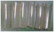
- Transpaente PVC Schläuche

Fader plastic stopper tubing
Das kommt seltenst vor, daß zu Geräuschdämpfung des Anschlags des Überblend-Hebels die Plastik-Hüllen / Schläuche über die Bolzen gezogen werden sollen. Dar Aufwand ist heute unbezahlbar.
.
RC4177 - Fan (Lüftertausch des großen Lüfters))
.
Exchanging Procedure
.
- Switch power off and disconnect cables.
- Turn the whole switcher over and loosen the 2 screws on the fan door.
- Lift the fan door and loosen the cable from the fan.
- Pull at the rubber and lift the fan out of the rubber mounting.
- Mount the new fan and put the fan door back.
- Connect the fan cable.
- Close the door and fasten the 2 screws.
- Turn the whole switcher over.
.
RY4150 - HiRes Board (CPU-Lüfter auf HD Einschub)
.
Exchanging Procedure
.
- Switch power off and disconnect cables.
- Loose 2 screws at the back.
- Pull out the High Resolution Board.
- Loose 4 screws at the fan and disconnect the cable.
- Mount the new Fan on it , fasten 4 screws and connect the cable.
- Push in the High Resolution board and fasten 2 screws.
.
RC4171 - Fan Power Supply (Kleiner Lüfter)
.
Exchanging Procedure
.
- Switch power off and disconnect cables.
- Turn the whole switcher over and loosen the 2 screws on the power supply door.
- Lift the power supply door and loosen the power connector.
- Loosen the power connector on the other side of the power supply door (2 yellow-green and 1 black cable).
- Loosen the fan connector.
- Pull at the rubber and lift the fan out of the rubber mounting.
- Mount the new fan in and put the fan door back.
- Connect the fan cable and all the power supply cables.
- Close the door and fasten the 2 screws.
- Turn the whole switcher over.
.
RC4193 - Power Supply (das Industrienetzteil)
Die gesamte Demontage des Netzteils ist extrem fummelig. Dazu braucht man eine Menge Geduld.
.
Exchanging Procedure
.
- Switch power off and disconnect cables.
- Turn the whole switcher over and loosen the 2 screws on the power supply door.
- Lift the power supply door and loosen the power connector.
- Loosen the power connector on the other side of the power supply door (2 yellow-green and 1 black cable).
- Loosen the fan connector and remove it.
- Loosen the 4 screws.
- Remove the protection covering from the new power supply.
- Carefully mount the new power supply on the metal part and fasten the 4 screws.
- Mount back the power supply door, connect the fan cable and all the power cables.
- Close the door and fasten the 2 screws.
- Turn the whole switcher over.
.
RY4121 - Processing Module (die CPU Huckepack-Karte)
Exchanging Procedure
.
- Switch power off and disconnect cables.
- Remove all soft knobs. Use a screwdriver to push upwards.
- Remove the 6 fader knobs and use your finger to push upwards.
After removing the fader knobs move the audio faders to the middle position. |
- Unscrew the screws on the right side of the fader grasp. Take the 2 metal pins off.
- Turn the whole switcher over and remove the 2 screws on the fan door.
- Lift the fan door and loosen the cable from the fan.
- Loosen the 2 screws on the power supply door.
- Lift the power supply door and loosen the power connector.
- Loosen the power connector on the other side of the power supply door (2 yellow-green and 1 black cable).
- Loosen the fan connector and remove it.
- Remove the cable holder.
- Loosen the 7 screws on the underside of the unit. Turn the Indigo the right way around and carefully lift the case up.
The Flash Card door will come loose. |
- Loosen the 8 screws on the RY4120.
- Lift the board package up and loosen the cable to the headphone connector.
- Loosen the ribbon cable from the display and carefully lift the board package upwards.
- Loosen the 14 screws and carefully lift the Switch Board upwards.
- Loosen the 4 Screws and the ribbon cable.
- Carefully lift the board upwards.
- Remove the protection covering from the new Processing Module.
- Carefully mount the new Processing Module on the RY4120 and fasten the 4 screws and connect the ribbon cable to the new Processing Module.
- Carefully mount the Switch Board on the RY4120 and fasten the 14 screws.
- Put the board package into the case and lift it up to reconnect the headphone cable and the ribbon cable to the display.
- Fasten the 8 screws on RY4120.
- Mount the underside of the case and fasten the 7 screws.
- Mount the cable holder.
- Mount the power supply door, connect the fan cable and all the power cables.
- Close the door and fasten the 2 screws.
- Mount the fan door and connect the fan cable.
- Close the door and fasten the 2 screws.
- Turn the whole switcher over.
- Mount the 2 pins at the fader and fasten the screw.
- Mount the 6 fader knobs.
- Remount all soft knobs.
.
RY4120 - Processor Board (das eigentliche Mainboard)
.
Exchanging Procedure
.
- Switch power off and disconnect cables.
- Remove all soft knobs. Use a screwdriver to push upwards.
- Remove the 6 fader knobs and use your finger to push upwards.
After removing the fader knobs move the audio faders to the middle position. |
- Unscrew the screws on the right side of the fader grasp. Take the 2 metal pins off.
- Turn the whole switcher over and remove 2 screws on the fan door.
- Lift the fan door and loosen the cable from the fan.
- Loosen the 2 screws on the power supply door.
- Lift the power supply door and loosen the power connector.
- Loosen the power connector on the other side of the power supply door (2 yellow-green and 1 black cable).
- Loosen the fan connector and remove it.
- Remove the cable holder.
- Loosen the 7 screws on the underside of the unit. Turn the Indigo the right way around and carefully lift the case up.
The Flash Card door will come loose. |
- Loosen the 8 screws on the RY4120.
- Lift the board package up and loosen the cable to the headphone connector.
- Loosen the ribbon cable from the display and carefully lift the board package upwards.
- Loosen the 2 screws on the back of the High Resolution Board and pull it out.
- Loosen the 19 screws and 28 BNC nuts on the back.
- Loosen the 8 hexagonal columns on the back.
At the Digital Audio I/O Connector are M3 Threads. |
- Turn the board package over and loosen the 2 screws on the RY4120.
- Remove the metal part from the back.
- Loosen the 14 screws and carefully lift the Switch Board upwards.
- Loosen the 4 screws and the ribbon cable on the RY4121.
- Carefully lift the board upwards.
- Turn the board package over.
- Loosen the 3 screws and carefully lift the Analog Audio Board upwards.
- Loosen the single hexagonal column and the single screw on the Digital Audio Board.
- Carefully lift the Digital Audio Board upwards.
- Turn the board package over and loosen the 10 screws.
- Turn over again and carefully lift the metal rack upwards.
- Remove the protection covering from the new Processor board.
- Move the Flash Card from the old RY4120 to the new one.
- Move the Power Supply cable to the new Processor board.
- Carefully mount the metal rack on the new RY4120.
- Carefully mount the Digital Audio Board and fasten the screw and the hexagonal column.
- Carefully mount the Analog Audio Board and fasten the 3 screws.
- Mount the RY4121 Processing Module and fasten the 4 screws.
- Carefully mount the Switch Board on the RY4120 and fasten the 14 screws.
- Mount the back metal part and fasten the 19 screws, 28 BNC nuts and the 8 hexagonal columns.
- Connect the 2 cables of the Power Entry Module to RY4120 and fasten the 2 screws.
- Mount the High Resolution Board and fasten the 2 screws.
- Put the board package into the case and lift it up to reconnect the headphone cable and the ribbon cable to the display.
- Fasten the 8 screws on RY4120.
- Mount the underside of the case and fasten the 7 screws.
- Mount the cable holder.
- Mount the power supply door, connect the fan cable and all the power cables.
- Close the door and fasten the 2 screws.
- Mount the fan door and connect the fan cable.
- Close the door and fasten the 2 screws.
- Turn the whole switcher over.
- Mount the 2 pins onto the fader and fasten the screw.
- Mount the 6 fader knobs.
- Remount all the soft knobs.
.
RY4110 - Switch Board (das obere Board mit den Tasten)
.
Exchanging Procedure
.
- Switch power off and disconnect cables.
- Remove all soft knobs. Use a screwdriver to push upwards.
- Remove the 6 fader knobs and use your finger to push upwards.
| After removing the fader knobs move the audio faders to the middle position. |
- Unscrew the screws on the right side of the fader grasp. Take the 2 metal pins off.
- Turn the whole switcher over and remove 2 screws on the fan door.
- Lift the fan door and loosen the cable from the fan.
- Loosen the 2 screws on the power supply door.
- Lift the power supply door and loosen the power connector.
- Loosen the power connector on the other side of the power supply door (2 yellow-green and 1 black cable).
- Loosen the fan connector and remove it.
- Remove the cable holder.
- Loosen the 7 screws on the underside of the unit. Turn the Indigo the right way around and carefully lift the case up.
| The Flash Card door will come loose. |
- Loosen the 8 screws on the RY4120.
- Lift the board package up and loosen the cable to the headphone connector.
- Loosen the ribbon cable from the display and carefully lift the board package upwards.
- Loosen the 14 screws and carefully lift the Switch Board upwards.
- Remove the protection covering from the new Switch Board.
- Turn the RY4110 over and loosen the cables on the audio fader.
- Lift the Audio Fader out and mount it on the new Switch board.
- Loosen the cable and the 4 screws on the joystick.
- Lift the Joystick out and mount it on the new Switch board.
- Loosen the cable on the fader.
- Turn the RY4110 over and loosen the 4 screws.
- Lift the Fader out and mount it on the new one.
- Carefully mount the new Switch Board on the RY4120 and fasten the 14 screws.
- Put the board package into the case and lift it up to reconnect the headphone cable and the ribbon cable to the display.
- Fasten the 8 screws on RY4120.
- Mount the underside of the case and fasten the 7 screws.
- Mount the cable holder.
- Mount the power supply door, connect the fan cable and all the power cables.
- Close the door and fasten the 2 screws.
- Mount the fan door and connect the fan cable.
- Close the door and fasten the 2 screws.
- Turn the whole switcher over.
- Mount the 2 pins onto the fader and fasten the screw.
- Mount the 6 fader knobs.
- Remount all soft knobs.
.
RC4189 - TFT Display with Touchscreen
.
Exchanging Procedure
.
- Switch power off and disconnect cables.
- Remove all soft knobs. Use a screwdriver to push upwards.
- Remove the 6 fader knobs and use your finger to push upwards.
After removing the fader knobs move the audio faders to the middle position. |
- Unscrew the screws on the right side of the fader grasp. Take the 2 metal pins off.
- Turn the whole switcher over and remove 2 screws on the fan door.
- Lift the fan door and loosen the cable from the fan.
- Loosen the 2 screws on the power supply door.
- Lift the power supply door and loosen the power connector.
- Loosen the power connector on the other side of the power supply door (2 yellow-green and 1 black cable).
- Loosen the fan connector and remove it.
- Remove the cable holder.
- Loosen the 7 screws on the underside of the unit. Turn the Indigo the right way around and carefully lift the case up.
The Flash Card door will come loose. |
- Loosen the 8 screws on the RY4120.
- Lift the board package up and loosen the cable to the headphone connector.
- Loosen the ribbon cable from the display and carefully lift the board package upwards.
- Loosen the 4 screws on the display and lift it up.
- Remove the gasket strips on the bezel.
- Disconnect the 2 cables and separate one of them from the cable tie.
- Loosen the 4 screws and disconnect the ribbon cable.
- Remove the protection covering from the new TFT Display.
- Mount the metal part on the new TFT Display and fasten the 4 screws.
- Connect the ribbon cable and the other cables.
- Put the Display back into the case and fasten the 4 screws.
- Put the board package into the case and lift it up to reconnect the headphone cable and the ribbon cable to the display.
- Fasten the 8 screws on RY4120.
- Mount the underside of the case and fasten the 7 screws.
- Mount the cable holder.
- Mount the power supply door, connect the fan cable and all the power cables.
- Close the door and fasten the 2 screws.
- Mount the fan door and connect the fan cable.
- Close the door and fasten the 2 screws.
- Turn the whole switcher over.
- Mount the 2 pins onto the fader and fasten the screw.
- Mount the 6 fader knobs.
- Remount all soft knobs.
.
Battery (die 3,3 Volt Knopfzelle / Stützbatterie)
.
Exchanging Procedure
.
- Turn the whole switcher over and remove 2 screws on the fan door.
- Lift the fan door and loosen the cable from the fan.
- Lift the battery in front and take it out.
.
Date and Time attitudes will be lost! |
- Put in the new battery.
- Mount the Case and fasten the 7 screws.
- Mount the fan door and connect the fan cable.
- Close the fan door and fasten the 2 screws.
- Turn the whole switcher over.
- The system clock needs to be readjusted.
.
RC4175 - Cable Set
Exchanging Procedure
.
- Headphone Cable
- Power Cable (Power Entry -> Power Supply)
- Power Cable (Power Supply -> Processor Board)
.
Exchange Procedure I:
.
Headphone Cable.
.
- Switch power off and disconnect cables.
- Remove all soft knobs. Use a screwdriver to push upwards.
- Remove the 6 fader knobs and use your finger to push upwards.
After removing the fader knobs move the audio faders to the middle position. |
- Unscrew the screws on the right side of the fader grasp. Take the 2 metal pins off.
- Turn the whole switcher over and remove 2 screws on the fan door.
- Lift the fan door and loosen the cable from the fan.
- Loosen the 2 screws on the power supply door.
- Lift the power supply door and loosen the power connector.
- Loosen the power connector on the other side of the power supply door (2 yellow-green and 1 black cable).
- Loosen the fan connector and remove it.
- Remove the cable holder.
- Loosen the 7 screws on the underside of the unit. Turn the Indigo the right way around and carefully lift the case up.
| The Flash Card door will come loose. |
- Loosen the 8 screws on the RY4120.
- Lift the board package up and loosen the cable to the headphone connector.
- Loosen the ribbon cable from the display and carefully lift the board package upwards.
- Loosen the 2 screws on the headphone connector and remove it.
- Mount the new Headphone Cable and fasten the 2 screws.
- Put the board package into the case and lift it up to reconnect the headphone cable and the ribbon cable to the display.
- Fasten the 8 screws on RY4120.
- Mount the underside of the case and fasten the 7 screws.
- Mount the cable holder.
- Mount the power supply door, connect the fan cable and all the power cables.
- Close the door and fasten the 2 screws.
- Mount the fan door and connect the fan cable.
- Close the door and fasten the 2 screws.
- Turn the whole switcher over.
- Mount the 2 pins onto the fader and fasten the screw.
- Mount the 6 fader knobs.
- Remount all soft knobs.
.
Exchange Procedure II:
.
Power Cable (Power Entry -> Power Supply)
.
- Switch power off and disconnect cables.
- Remove all soft knobs. Use a screwdriver to push upwards.
- Remove the 6 fader knobs and use your finger to push upwards.
After removing the fader knobs move the audio faders to the middle position. |
- Unscrew the screws on the right side of the fader grasp. Take the 2 metal pins off.
- Turn the whole switcher over and remove 2 screws on the fan door.
- Lift the fan door and loosen the cable from the fan.
- Loosen the 2 screws on the power supply door.
- Lift the power supply door and loosen the power connector.
- Loosen the power connector on the other side of the power supply door (2 yellow-green and 1 black cable).
- Loosen the fan connector and remove it.
- Remove the cable holder.
- Loosen the 7 screws on the underside of the unit. Turn the Indigo the right way around and carefully lift the case up.
The Flash Card door will come loose. |
- Loosen the 8 screws on the RY4120.
- Lift the board package up and loosen the cable to the headphone connector.
- Loosen the ribbon cable from the display and carefully lift the board package upwards.
- Loosen the 2 screws on the back of the High Resolution Board and pull it out.
- Loosen the 19 screws and 28 BNC nuts on the back.
- Loosen the 8 hexagonal columns on the back.
At the Digital Audio I/O Connector are M3 Threads. |
- Loosen the 2 screws on the RY4120.
- Remove the metal part from the back.
- Loosen the 2 cables on the Power Entry Module and 3 (1 black and 2 green/yellow) on the metal part.
- Connect the new Power Cable to the Power Entry Module.
- Mount the back metal part and fasten the 19 screws, 28 BNC nuts and the 8 hexagonal columns.
- Connect the 2 cables of the Power Entry Module to RY4120 and fasten the 2 screws.
- Mount the High Resolution Board and fasten the 2 screws.
- Put the board package into the case and lift it up to reconnect the headphone cable and the ribbon cable to the display.
- Fasten the 8 screws on RY4120.
- Mount the underside of the case and fasten the 7 screws.
- Mount the cable holder.
- Mount the power supply door, connect the fan cable and all the power cables.
- Close the door and fasten the 2 screws.
- Mount the fan door and connect the fan cable.
- Close the door and fasten the 2 screws.
- Turn the whole switcher over.
- Mount the 2 pins onto the fader and fasten the screw.
- Mount the 6 fader knobs.
- Remount all soft knobs.
.
Exchange Procedure III:
.
Power Cable (Power Supply -> Processor Board)
.
- Switch power off and disconnect cables.
- Turn the whole switcher over and remove 2 screws on the fan door.
- Lift the fan door and loosen the cable from the fan.
- Loosen the 2 screws on the power supply door.
- Lift the power supply door and loosen the power connector.
- Loosen the power connector on the other side of the power supply door (2 yellow-green and 1 black cable).
- Loosen the fan connector and remove it.
- Remove the cable holder.
- Loosen the 7 screws on the underside of the unit. Turn the Indigo the right way around and carefully lift the case up.
The Flash Card door will come loose. |
- Loosen the Power Cable from the Processor Board.
- Connect the new Power Cable on the Processor Board.
- Mount the Case and fasten the 7 screws.
- Mount the cable holder.
- Mount the power supply door, connect the fan cable and all the power cables.
- Close the door and fasten the 2 screws.
- Mount the fan door and connect the fan cable.
- Close the door and fasten the 2 screws.
- Turn the whole switcher over
.
RY4125 - Connection Board
.
Exchanging Procedure
.
- Switch power off and disconnect cables.
- Remove all soft knobs. Use a screwdriver to push upwards.
- Remove the 6 fader knobs and use your finger to push upwards.
After removing the fader knobs move the audio faders to the middle position. |
- Unscrew the screws on the right side of the fader grasp. Take the 2 metal pins off.
- Turn the whole switcher over and remove 2 screws on the fan door.
- Lift the fan door and loosen the cable from the fan.
- Loosen the 2 screws on the power supply door.
- Lift the power supply door and loosen the power connector.
- Loosen the power connector on the other side of the power supply door (2 yellow-green and 1 black cable).
- Loosen the fan connector and remove it.
- Remove the cable holder.
- Loosen the 7 screws on the underside of the unit. Turn the Indigo the right way around and carefully lift the case up.
The Flash Card door will come loose. |
- Loosen the 8 screws on the RY4120.
- Lift the board package up and loosen the cable to the headphone connector.
- Loosen the ribbon cable from the display and carefully lift the board package upwards.
- Loosen the 2 screws on the back of the High Resolution Board and pull it out.
- Loosen the 19 screws and 28 BNC nuts on the back.
- Loosen the 8 hexagonal columns on the back.
At the Digital Audio I/O Connector are M3 Threads. |
- Loosen the 2 screws on the RY4120.
- Remove the metal part from the back.
- Loosen the 14 screws and carefully lift the Switch Board upwards.
- Turn the board package over.
- Loosen the 3 screws and carefully lift the Analog Audio Board upwards.
- Turn the board package over and loosen the 10 screws.
- Turn the board over and carefully lift the metal rack upwards and loosen the 4 screws.
- Remove the protection covering from the new Connection board.
- Fasten the new Connection board with 4 screws.
- Carefully mount the metal rack on the RY4120 and fasten the 10 screws.
- Carefully mount the Analog Audio Board and fasten the 3 screws.
- Carefully mount the Switch Board back and fasten the 14 screws.
- Mount the back metal part and fasten the 19 screws, 28 BNC nuts and the 8 hexagonal columns.
- Connect the 2 cables from the Power Entry Module to RY4120 and fasten the 2 screws.
- Mount the High Resolution Board and fasten the 2 screws.
- Put the board package into the case and lift it up to reconnect the headphone cable and the ribbon cable to the display.
- Fasten the 8 screws on RY4120.
- Mount the underside of the case and fasten the 7 screws.
- Mount the cable holder.
- Mount the power supply door, connect the fan cable and all the power cables.
- Close the door and fasten the 2 screws.
- Mount the fan door and connect the fan cable.
- Close the door and fasten the 2 screws.
- Turn the whole switcher over.
- Mount the 2 pins onto the fader and fasten the screw.
- Mount the 6 fader knobs.
- Remount all soft knobs.
.
Display Connection Cable
.
Exchanging Procedure
.
- Switch power off and disconnect cables.
- Remove all soft knobs. Use a screwdriver to push upwards.
- Remove the 6 fader knobs and use your finger to push upwards.
After removing the fader knobs move the audio faders to the middle position. |
- Unscrew the screws on the right side of the fader grasp. Take the 2 metal pins off.
- Turn the whole switcher over and remove 2 screws on the fan door.
- Lift the fan door and loosen the cable from the fan.
- Loosen the 2 screws on the power supply door.
- Lift the power supply door and loosen the power connector.
- Loosen the power connector on the other side of the power supply door (2 yellow-green and 1 black cable).
- Loosen the fan connector and remove it.
- Remove the cable holder.
- Loosen the 7 screws on the underside of the unit. Turn the Indigo the right way around and carefully lift the case up.
The Flash Card door will come loose. |
- Loosen the 8 screws on the RY4120.
- Lift the board package up and loosen the cable to the headphone connector.
- Loosen the ribbon cable from the display and carefully lift the board package upwards.
- Loosen the 14 screws and carefully lift the Switch Board upwards.
- Loosen the display cable from the Processing Module.
- Connect the new display ribbon cable from the Processing Module.
- Carefully mount the Switch Board on the RY4120 and fasten the 14 screws.
- Put the board package into the case and lift it up to reconnect the headphone cable and the ribbon cable to the display.
- Fasten the 8 screws on RY4120.
- Mount the underside of the case and fasten the 7 screws.
- Mount the cable holder.
- Mount the power supply door, connect the fan cable and all the power cables.
- Close the door and fasten the 2 screws.
- Mount the fan door and connect the fan cable.
- Close the door and fasten the 2 screws.
- Turn the whole switcher over.
- Mount the 2 pins onto the fader and fasten the screw.
- Mount the 6 fader knobs.
- Remount all soft knobs.
.
Fuse Drawer (die Netzsicherungen an der Netz-Buchse)
Hier aufpassen, im Netzteil gibt es auch noch mal eine primäre 230V Netzsicherung
.
Exchanging Procedure
.
- Switch the power off and disconnect the cables.
- Push the mounting apart and pull out the Fuse Drawer.
- Pull out the fuses.
- Insert the fuses into the new Fuse Drawer.
- Push Fuse Drawer into the Power Entry Module.
.
Joystick austauschen
.
Exchanging Procedure
.
- Switch power off and disconnect cables.
- Remove all soft knobs. Use a screwdriver to push upwards.
- Remove the 6 fader knobs and use your finger to push upwards.
After removing the fader knobs move the audio faders to the middle position. |
- Unscrew the screws on the right side of the fader grasp. Take the 2 metal pins off.
- Turn the whole switcher over and loosen the 2 screws on the fan door.
- Lift the fan door and loosen the cable from the fan.
- Loosen the 2 screws on the power supply door.
- Lift the power supply door and loosen the power connector.
- Loosen the power connector on the other side of the power supply door (2 yellow-green and 1 black cable).
- Loosen the fan connector and remove it.
- Remove the cable holder.
- Loosen the 7 screws on the underside of the unit. Turn the Indigo the right way around and carefully lift the case up.
The Flash Card door will come loose. |
- Loosen the 8 screws on the RY4120.
- Lift the board package up and loosen the cable to the headphone connector.
- Loosen the ribbon cable from the display and carefully lift the board package upwards.
- Loosen the 14 screws and carefully lift the Switch Board upwards.
- Turn the RY4110 over and loosen the cable and the 4 screws.
- Lift the Joystick out and put the new one in.
- Fasten the 4 screws and the cable.
- Carefully mount the Switch board on the RY4120 and fasten the 14 screws.
- Put the board package into the case and lift it up to reconnect the headphone cable and the ribbon cable to the display.
- Fasten the 8 screws on RY4120.
- Mount the underside of the case and fasten the 7 screws.
- Mount the cable holder.
- Mount the power supply door, connect the fan cable and all the power cables.
- Close the door and fasten the 2 screws.
- Mount the fan door and connect the fan cable.
- Close the door and fasten the 2 screws.
- Turn the whole switcher over.
- Mount the 2 pins onto the fader and fasten the screw.
- Mount the 6 fader knobs.
- Remount all soft knobs.
.
Position Controller Lens for Joystick
.
Exchanging Procedure
.
- Switch power off and disconnect cables.
- Remove all soft knobs. Use a screwdriver to push upwards.
- Remove the 6 fader knobs and use your finger to push upwards.
After removing the fader knobs move the audio faders to the middle position. |
- Unscrew the screws on the right side of the fader grasp. Take the 2 metal pins off.
- Turn the whole switcher over and loosen the 2 screws on the fan door.
- Lift the fan door and loosen the cable from the fan.
- Loosen the 2 screws on the power supply door.
- Lift the power supply door and loosen the power connector.
- Loosen the power connector on the other side of the power supply door (2 yellow-green and 1 black cable).
- Loosen the fan connector and remove it.
- Remove the cable holder.
- Loosen the 7 screws on the underside of the unit. Turn the Indigo the right way around and carefully lift the case up.
The Flash Card door will come loose. |
- Loosen the 8 screws on the RY4120.
- Lift the board package up and loosen the cable to the headphone connector.
- Loosen the ribbon cable from the display and carefully lift the board package upwards.
- Loosen the 14 screws and carefully lift the Switch Board upwards.
- Turn the RY4110 over and loosen the cable and the 4 screws.
- Lift the Joystick out and loosen the 4 screws.
- Mount the new Position Controller Lens on the Joystick and fasten the 4 screws.
- Put the Joystick back on the RY4110 and fasten the 4 screws and the cable.
- Carefully mount the Switch board on the RY4120 and fasten the 14 screws.
- Put the board package into the case and lift it up to reconnect the headphone cable and the ribbon cable to the display.
- Fasten the 8 screws on RY4120.
- Mount the underside of the case and fasten the 7 screws.
- Mount the cable holder.
- Mount the power supply door, connect the fan cable and all the power cables.
- Close the door and fasten the 2 screws.
- Mount the fan door and connect the fan cable.
- Close the door and fasten the 2 screws.
- Turn the whole switcher over.
- Mount the 2 pins onto the fader and fasten the screw.
- Mount the 6 fader knobs.
- Remount all soft knobs.
.
Spare Parts List
Type | Designation | Order Number |
|---|---|---|
| ||
F R U (field replacable units - beim Kunden tauschbar) | ||
RC 4177 | Fan Frame | 000 219 417 710 |
RC 4182 | 1:1 Cable for Tally Adapter | 000 219 418 210 |
RC 4183 | Digital Audio Adapter Cable | 000 219 418 310 |
RC 4184 | Tally Breakout Adapter Set | 000 219 418 410 |
RC 4190 | CD-ROM (Software + Manual) | 000 219 419 000 |
RC 4191 | Printed Manual | 000 219 419 110 |
RC 4192 | CompactFlash Card 512MB Spare Part | 000 219 419 210 |
RC 4197 | Wearing Parts | 000 219 419 710 |
RY 4140 | High Resolution Board | 000 219 414 010 |
| INDIGO AV Switcher HD | 000 219 410 110 |
| INDIGO AV Switcher SD | 000 219 410 010 |
| KEY SET | 002 219 410 010 |
| Lithium Battery 3V 180mAh CR2032 | 003 119 102 010 |
| Wall-plug-in PwrSupply | 003 119 104 090 |
| ||
Assembly Level | ||
RC 4171 | Fan Power Supply Unit | 000 219 417 110 |
RC 4161 | Display cpl. | 000 219 416 011 |
RC 4189 | TFT Display with Touch Screen Spare Part | 000 219 419 411 |
RC 4116 | Audio Fader (with Motor) | 000 219 411 610 |
RC 4126 | Fan complete | 000 219 412 610 |
RC 4175 | Cable Set Power/Headphone | 000 219 417 510 |
RC 4193 | Power Suppply Spare Part | 000 219 419 310 |
RC 4195 | ENCLOSURE TOP CASE CPL. Spare Part | 000 219 419 510 |
RC 4196 | ENCLOSURE LOWER CASE Spare Part | 000 219 419 610 |
RY 4110 | Switch Board Set | 000 219 411 010 |
RY 4120 | Processor Board Spare Part | 000 219 412 010 |
RY 4121 | Processing Module | 000 219 412 110 |
RY 4125 | Connection Board | 000 219 412 510 |
RY 4130 | Digital Audio Board | 000 219 413 010 |
RY 4150 | Analog Audio Board | 000 219 415 010 |
| Display Connection Cable 2x25pole | 005 136 391 021 |
| Flat Cable 8pos. 60mm | 005 136 391 016 |
| Lever arm complete/Fader from GVG NC | 003 111 201 926 |
| Miniature Finger Joystick | 003 111 201 927 |
| Position Controller Lens for Joystick | 001 219 410 020 |
| Power Entry Module Type KMF, 6A | 003 119 103 329 |
| HiRes Board Fan | 85569710 |
| Fader plastic stopper tubing Kit | 075089200 |