
Die "Time-Code" Technik betrifft nur die Video- und Audiorecorder der professionellen Anwender.
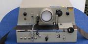
- Der mech. Schnittplatz mit Scope


- Die Klebefolie für den Schnitt

Und eigentlich gehört der technische Teil dieses Konzeptes in unser Magnet- bandmuseum. Doch auch dort betrifft sie nur den ganz kleinen Teil der Fernsehleute, die eine Epoche lang auf Magnetband aufgenommen hatten und die die ganz frühen Video-Filme bzw. Sendungen aus einzelnen Stücken zusammenbauten - also wie beim Film "schneiden" - mußten. Und dafür gab es richtige 2" Videoband- Schneidemaschinen. Wir haben 2 Stück von diesen wirklich seltenen Unikaten geerbt, die große Maschine aus Köln und die kleine Maschine aus der Schweiz vom Schweizer Fernsehen.
"Natürlich" ging das mit dem 35mm und dem 16mm Film (angeblich) alles viel schneller, doch auch dort hatte man seine logistischen und auch technischen Probleme - mit dem synchronen Ton auf dem separat laufenden Magnetfilmen und den zugehörigen Cord-Läufern zum Beispiel.
Eine perfekte Schnitt-Logistik war die Voraussetzung für die Schnittechnik. Und weil bei der Entwicklung eines nahezu perfekten und auch noch transportablen Time-Codes die Logik des Time-Codes wesentlich wichtiger war als die spätere Realisierung auf dem Magnetband, ist diese Time-Code Entwicklung und die Erklärung dazu (in englisch) für die Fernsehleute im Video-Bereich hier im Fernsehmuseum enthalten.
Die Idee war gut, jedoch es gab eine Menge Hinkefüße.

- Die Klappe

Ganz am Anfang wollte man auf dem Video-Band "ja nur" - wie beim 35m Film - die einzelnen Bilder durchnummerieren. Beim Film war aber am Anfang immer "die Klappe" mit dem Film-Titel und der laufenden Nummer des Takes drauf. Im schnellen Fernsehen war das aber sehr oft gar nicht machbar, wenn gerade ein Unwetter losschlug oder das qualmende Flugzeug - ohne den Kameramann zu fragen - einfach einlandete.
Solch ein Kamera-Team brachte dann eine Menge sogenannter Schnipsel oder Takes auf dem Band oder den Bändern mit zurück ins Studo und nun gings los. Die Schnipsel sollten zu einem mehr oder weniger kleinen Film zusammengefügt - "geschnitten" - werden.
Das Mindeste wäre doch ein Code auf dem Videoband, auf dem das Datum und die Uhrzeit unlöschbar mit drauf wären. Dann könnte man ja auch beim Schneiden viel einfacher arbeiten, in dem man sich nur die beiden Anfang-Ende Eckdaten eines verwertbaren Auschnittes eines jeden Schnipsels aufschreibt und natürlich die Reihenfolge, in der diese Schnipsel aneinander gereiht werden sollen.
Kling gut, aber wir sind noch zwischen 1957 und 1960.
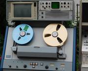
- Die AMPEX VPR 1100 etwa 1960

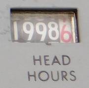
- Hier war jemand das volle Risiko oberhalb der 1500 Std eingegangen

Die Bild-Ingenieure, die sich mit dem mechanischen Video-Schnitt herumquälen mußten und die sich das mit dem Timecode deshalb bereits 1958/59 ausgedacht hatten, hatten die Rechnung leider ohne den Wirt gemacht. Oder vielleicht doch mit dem Wirt, der möglichst viel verdienen möchte oder wollte ? Die Technik war noch nicht so weit.
Die allererste und wichtigste Randbedingung war, daß die ganz frühen 2" Videorecorder von AMPEX und RCA etwa 150 Stunden echte Betriebszeit für ein ganz neues Kopfrad mit den vier Videoköpfen hatten. (Später hatten die 1" Recorder etwa 1.500 Stunden.)
Das Ampex-4-Kopfrad drehte damals irrsinnig schnell und die 4 Video-Köpfe verschlissen auch schnell, nach heutigen Maßstäben. Wenn dann die Bildmeßtechnik eines Senders solch einen Ampex 2" Recorder mehrere Stunden einmessen mußte, weil eine ganz ganz wichtige Schow (sogar mit 2 Recordern gleichzeitig) aufgenommen werden mußte (zum Beispiel : Der goldene Schuss im ZDF), fing der technische Direktor schon - mit der Faust in der Hosentasche - an zu zittern.
Denn solch eine Ampex 150 Stunden Kopftrommel kostet jedes Mal ca. 6.000 Dollar, wenn die Köpfe "runter" waren. Und jetzt versteht sogar der Laie, es war damals eine teure Technik mit den ersten professionellen 2" Video-Recordern.
Wenn man solche Schittversuche simulieren könnte, ja dann ...
Hätte man auf dem originalen Videoband eindeutige Positions-Codes drauf, könnte man solch ein "Filmchen" mit Lowcost Video-Recordern und diesem stundenlangen vor und zurück - wie beim Film - simulieren und hatte am Ende - auch noch viel flexibler und schneller - das ausgefuchste und perfekt eindeutige "Schnittprotokoll" fix und fertig vorliegen. Dann brauchte man die großen teuren 2" Profi-Recorder nur ein einziges Mal durchlaufen zu lassen und hätte die edle Studioqualität quasi zum Discountpreis "im Kasten" - also am Stück sendefertig auf dem neuen Schnittband drauf.
Das also und noch etwas mehr steckte an Ideen in einem ausgefuchsten sogenannten "Time-Code". Der nachfolgende Artikel, ein kleines Büchlein aus 1992 erzählt auch von den Anfängen und der Einbringung von Forderungen und Ideen mehrerer Beteiligter (auf der ganzen Welt).
.
THE TIME CODE BOOK
A SHORT HISTORY AND TECHNICAL UPDATE ON THE LATEST ADVANCES IN THE SMPTE/EBU TIME CODE.
By the innovators who put time code to work for the video and audio recording industries.
Title :
SMPTE/EBU Longitudinal & Vertical Interval Time Code
Computer Controls for Video Production
IN THE BEGINNING . . .
EDITING-FROM 1956 TO 1967 B.C. (BEFORE TIME CODE):
In 1956, videotape recording made its debut (Der 2" revoder von Ampex). Almost immediately, producers who pioneered the use of the new medium recognized that the time-honored cut-and-splice methods - that afforded (verlangt) so much creative freedom in the film medium - were inaccurate, cumbersome and time consuming when applied to video tape.
For one thing, the recorded images on video tape were not directly visible like they were on film. (Ein Einzel-Bild warauf 4 Videopöpfe verteilt und konnt nur im laufendenBetrieb angezeigt werden.) So it was difficult to locate the proper splice points (Schnittstellen). And even when the proper points were located, the resulting splices often produced a breakup or jump in the picture because of frame-to-frame mis-match at the splice (an der Schnittstelle).
Throughout the remainder of the 1950's, videotape editing continued to be a cut-and-splice process. To be sure, improvements were introduced which made the editor's life a little bit easier:
Magnetic inks were developed, which could be painted onto the tape to make the recorded tracks visible, and a standardized frame pulse- carried on a separate control track provided an electronic mark at the start of each frame. But, despite these advances, video tape editing remained a slow, tedious job.
Um 1960 wurde der elektronsiche Schnitt eingführt
In the early 1960's, electronic splicing systems were introduced. These systems were able to transfer recorded program material from one VTR to another under precise controls that ensured perfect frame-to-frame match-up at the splice point.
But before this little feat of magic could be performed, the splice point had to be searched-out through trial and error and marked (with electronic tones in this case), just as always. What was really needed was an electronic equivalent to the edge numbers used on film, so that each video frame could be uniquely identified for fast electronic searching and synchronization. Enter, space-age computer technology and EECO.
.
EECO AND THE BIRTH OF SMPTE TIME CODE:
(das Büchlein wurde von der Firma "EECO" geschrieben)
"EECO" designed the first practical timecode editing system in 1967. Called ON-TIME", the system utilized a time code concept similar to that employed by NASA to time-tag telemetry tapes recorded by its global tracking network during Gemini and Apollo missions.
With the ON-TIME system, searching to a specific video frame (das ist ein komplettes Einzelbild) to perform an edit was simply a matter of entering the corresponding time code number and allowing the system to run the tape to that number.
Edit points could be previewed and, if unsatisfactory, trimmed by as little as one frame at a time, just by altering the time code entries. The time code also provided the ON-TIME system with the electronic reference points needed to properly synchronize the VTRs for perfect frame-to-frame match-ups at the edit point.
Indeed, for a number of years after ON-TIME's introduction, time code editing was generically referred to as EECO editing because of its widespread acceptance by the video production community.
However, as time code came into general use, VTR manufacturers introduced their own coding schemes, all incompatible not only with the EECO code, but also with one another.
Die "Society of Motion Picture and Television Engineers" übernimmt
In early 1969, the "Society of Motion Picture and Television Engineers" (SMPTE) acted to end the chaos by establishing a committee to develop a standard code that would provide interchangeability.
The resulting standard was also adopted by the "European Broadcasting Union" (EBU), making it a truly international standard. The SMPTE/EBU code, as the standard is called, is the basis for all of today's sophisticated video and audio tape editing and synchronization systems.
THE WHYS AND HOWS OF SMPTE/EBU TIME CODE
WHY IS SMPTE/EBU TIME CODE SO IMPORTANT TO EDITING?
The answer to this question can be stated in just two words:
Accuracy and Repeatability.
Prior to the advent of time code (and even under some circumstances, today), elecronic editing systems utilized two basic increment/decrement indexing methods for rapid, automatic location of edit points: They either counted electronic pulses from a tachometer coupled to the VTR tape transport mechanism, or they counted control track pulses or mark tones recorded directly on the tape.
The trouble is, these methods rely upon maintaining an accurate count from a fixed starting point (of the tape). This count can be upset by tape slippage during rewind or cueing, or by signal dropouts on the tape. And the counting errors are cumulative, meaning that every individual counting error adds to the magnitude of the overall indexing error.
.
Der Identifier für jeden einzelnen Video-Rahmen (frame)
The SMPTE/EBU code solved this problem by providing each video frame with its own unique identification. Consisting of a binary pulse coded electronic signal, the SMPTE/EBU code is recorded on the videotape along with the corresponding video and audio signals.
It identifies every single video frame by hour, minute, second and frame.
Bild
.
Ganz klare und eindeutige Vorteile
This approach produces some distinct advantages:
1. Time reference is precise. The duration of a selected scene or program interval can be determined with frame accuracy. It can be determined, to the frame, how much unrecorded tape is available for a program segment. As a program is shot, or before it is edited, a scene schedule can be blocked-out so that postproduction personnel can run program tapes to the desired edit points with a minimum of time-consuming searching.
2. Time code allows interchangeability between editing systems. The IN and OUT points for edits selected on one editing system can be listed by their time code designations (either in a written list or on some type of electronic medium) and input to another editing system.
The edits performed by the second system will be identical to those selected on the first, whether the two editing systems are in the same room or half a world apart.
This interchangeability is also the key to a time and money saving process called auto-assembly. Using this process, programs can be mastered on high quality (and expensive-to-operate) VTRs (Anmerkung : Der Kopfverschleiß zählt pro Betriebsstunde und kostet richtig viel Geld.) and then dubbed down with the same time code onto an inexpensive tape format (like 3/4-inch cassette) to prepare a "workprint" for editing.
.
- Anmerkung : Das Ganze funktionierte aber erst, nachdem SONY bei den U-Matic Recordern eine Time-Code Variante auf den Markt brachte.
.
Off-Line Editing (Schneiden) on low-cost equipment
Editing on low-cost equipment (dort sind die Video-Köpfe auf der Video-Trommel wesentlich billiger und haben eine deutlich längere Standzeit.), the production team can work as carefully as it wishes, without regard for the amount of running time being put on the VTRs. This is called off-line editing.
The edit list that results from the off-line editing session is then input to an editing system controlling high-quality VTRs on which the master tapes have been mounted (an on-line editing system). Since the time code in the off-line edit list corresponds directly to the time code on the master tapes, the edits performed off-line will be duplicated on the master tapes.
And, because there is no human decision making at this point, all of the on-line edits are performed as fast as the VTRs can run the tape to the designated edit locations; this reduces expensive "running time" on the mastering VTRs to the absolute minimum. An extra dividend of the auto-assembly process is that the irreplaceable master tapes are never touched during the actual edit decision-making process, and are thus protected from accidental erasure or over-recording.
Kompatibilität und Transportablität
3. Time code allows precision synchronization of one VTR to another. The time code acts as "electronic sprocket holes", providing the means for an editing system or synchronization unit to bring two (or more) tapes into exact sync automatically. This means perfect frame-to-frame match-ups at the edit points; hence, clean edits that exhibit no video breakup.
"preroll" - Wenn Recorder unterschiedlich schnell laufen ....
To achieve this degree of synchronization, SMPTE/EBU code editing systems employ comparator circuits which look at the time code from each tape that is in motion. The comparators make real-time edit code calculations to judge the relative distance of each tape from the sync point at any given instant, and constantly issue slowdown/speed-up commands to the VTRs to keep all tapes in sync.
During initial synchronization, some of the VTRs involved may be speeded-up or slowed down as much as 50% over or under normal play speed in order to achieve syncronisation.
This initial sync-up process normally occurs during a short period just prior to reaching the edit IN point. This period is called the preroll.
With so many advantages to offer, it is little wonder that the SMPTE/EBU time code has become so critical to the operation of professional quality computer assisted editing systems. These systems utilize the time code's precise indexing not only to control tape decks in the performance of cues, previews, edits and replays, but also to trigger video switchers and special effects generators in the performance of wipes, dissolves, keys, flips, and other dazzling edit transitions. All automatically, and accurate to the frame.
WHAT DOES SMPTE/EBU CODE LOOK LIKE?
WHAT KIND OF INFORMATION IS ENCODED,
AND HOW IS IT DECIPHERED?
Now that you're familiar with how the SMPTE/EBU time code evolved and also have some idea of how it is used in frame-accurate editing systems, let's take a closer look at the code's make-up and inner workings.
Es gibt zwei Versionen oder Varianten des "Time-Codes"
To begin with, there are two versions of the SMPTE/ EBU time code: one is recorded on an audio track of the video tape and is called longitudinal (serial) time code; the other is recorded on the video tracks, and is called vertical interval time code (VITC).
Despite the different recording methods, the two versions of the code are quite similar in form and content. Owing to this fact, we will describe the longitudinal time code in detail, and then extend the description to the VITC by comparing the two.
Der "LONGITUDINAL TIME CODE" : (80 bits)
The longitudinal time code is an electronic signal that switches from one voltage to another, forming a string of pulses. Each one-second long chunk ("Brocken" oder "Klumpen" aufgetilt in Scheiben) of this signal is "sliced" (zerschnitten oder aufgeteilt) into 2.400 equal parts when the code is being used with the USA television standard of 30 fames per second (called NTSC), or 2.000 equal parts when used with the European standard of 25 frames per second (called PAL/SECAM).
Each slice of the time code signal is referred to as a bit. With some simple arithmetic, we can see that each video frame coincides with 80 time code bits:
NTSC 2.400 bits/sec / 30 frames/sec = 80 bits/frame
NTSC 2000 bits/sec / 25 frames/sec = 80 bits/frame
Most of these 80 bits have specific values assigned to them. However, these values are counted only if the time code signal changes from one voltage to the other in the middle of the bit period, forming a 1/2-bit pulse.
If the voltage remains at one value or the other through an entire bit period, that bit's assigned value won't be counted. In computer parlance, a 1/2-bit pulse represents a digital "1", while a full bit pulse represents a digital "0".
.
Die Grafiken sollen das besser erläutern
Let's take a look at how all these bits are deciphered by examining one frame's worth of time code (80 bits).
Breaking this frame down into its various parts, we get the following information:
bits zero through 3 and 8 and 9 are assigned to the frame count. Bit zero is assigned a value of 1, bit 1 a value of 2, bit 2 a value of 4, bit 3 a value of 8, bit 8 a value of 10 and bit 9 a value of 20.
Notice that in the example bits 0, 1 and 9 contain digital "1s" (i.e., the voltage level has switched in the middle of the bits, forming half-pulses). Only the values of these "1" bits will be counted; if we add the values of these bits ... 1+2+20 ... we get 23, the frame count of this particular frame.
Bits 16 through 19 and 24 through 26 tell us : this is the 31st second.
.
Bits assigned to the minute count show that this is the 47th minute.
And, finally, the Hours bits show us that this is the 16th hour.
Das Ergebnis ist der eindeutige Zeit-Code
Put all this together - as an electronic time code reader would, and the indexing on this particular frame reads "16th hours, 47th minute, 31st second and 23rd frame".
Das "sync word" im Time-Code
Bits 64 through 79 are always the same in every frame. They form a special pattern of "1" and "0" bits called the sync word. The sync word tells the decoding circuits in an electronic time code reader that this is the end of one frame and the start of another. It also indicates whether the tape is moving forward or reverse.
.
Besides the main groups of indexing bits that we have just discussed, there are several other bits and bit groups scattered through the time code frame that have special significance to time code systems equipped to use them.
.
The "drop frame bit"
Bit number 10 is called the drop frame bit. It tells electronic time code reading systems whether the code was recorded in drop-frame of non-drop frame format. A couple of definitions are in order here; what is drop-frame and non-drop frame time code?
Es ist gar nicht so kompliziert - als sooo tricky
It's really not too tricky. The time code is normally produced by a generator which counts at 30 frames-per-second (NTSC) of 25 frames-per-second (PAL/SECAM), synchronized to the same studio sync source as the VTRs.
However, NTSC color signals have an actual frequence of close to 29.97 frames-per-second. So a generator counting at 30 frames-per-second would produce an increasing error as time went on (3.6 seconds every hour). To compensate for this error build-up, a certain number of frames are eliminated from the time code each hours to shorten the time code and make it match clock time. Since 3.6 seconds equals 108 frames, then 108 frames must be eliminated from the time code each hour.
To accomplish this, two frames per minute are dropped each minute, every hour around the clock except every 10th minute. The reason for the 10th minute exception is that if two frames were dropped every minute of each hour, 120 frames would be dropped instead of the desired 108 frames.
The frame dropping occurs only at the changeover points from minute to minute. For example, when the time code changes from 01:08:59:29, the next frame number identified in drop format would be displayed as 01:09:00:02. In drop-frame time code, frames 00 and 01 don't exist. This effectively shortens the time code so that it agrees with standard clock time.
Time code generated in the drop-frame format is identified by placing a digital "1" in bit 10 of every frame of code so generated, to alert the equipment used in subsequent reading and synchronizing operations to account for the missing frame numbers. If the code is generated in non-drop frame format, a digital "0" is placed in bit 10 of every frame.
The "color frame bit" ist Nummer 11
Bit number 11 is the color frame bit. Applicable only to color recordings it tells electronic time code reading systems whether or not color frame identification has been applied intentionally.
A color frame is four fields - -1/15 second - - in NTSC; in PAL/SECAM, a color frame is eight fields - - 1/6 second.
Fields 1 and 3 are defined as color frame A, while fields 2 and 4 are defined as color frame B. A digital "1" is recorded in bit 11 to indicate that color frame identification has been applied to the time code. Color frame identification of the code indicates that even frame numbers coincide with color frame A and odd frame numbers coincide with color frame B. This identification helps video tape editing systems to maintain the correct video signal color burst phase relationship across the edit points. The editing system corrects for improper color framing during an edit by "bumping" the servo system of the record VTR during the VTR synchronization process that occurs during the preroll.
Failure to achieve proper color framing will result in a flash or flicker in the television picture at the edit IN point. It should be noted that some VTRs have built-in color framers and that most SMPTE/EBU videotape editing systems have a color framer that need to be set-up for correct color burst phasing only once when a new tape is mounted on the record VTR. In both cases, the color frame bit is not used, and should be set to digital "0" in all time code frames.
.
Einfügungen in den 80-bit Rahmen - die user-bits
Interspersed (eingefügt) through each 80-bit frame of time code are eight groups of four bits each. These 32 bits are referred to a user bits. The user bits are essentially leftovers; the time code can meet all of the indexing requirements imposed on it without filling these bits with data. This leaves the user bits available for any auxiliary function the user may have in mind.
The user bits can generally accommodate data for four alphabetical characters or eight numerical digits, or a combination of the two. They can be used to designate such things as reel numbers, recording date, or any other information that can be expressed in four letter or eight digits. In order to access the user bits, you MUST use time code equipment designed to generate and read them.
User bit data must be recorded simultaneous with the recording of the rest of the time code information; it can't be added once the code is on the tape. So it's important that the time code generator be set-up to produce the desired user bit data at the desired time code frames. If the user bits are not used, they should all be set to digital "0".
Der "VERTICAL INTERVAL TIME CODE" (VITC) : (90bits)
As has already been noted, VITC is very similar in composition to the longitudinal time code. It does, however, include several extra "housekeeping" bits that bring its total number of bits per frame to 90.
2 "sync bits"
Also note that, in the VITC, each of the nine data-carrying bit groups is preceded by two sync bits. These sync bits are always set to digital "1" and digital "0", respectively.
Ein "field bit"
Another difference between VITC and longitudinal time code is that VITC includes a very useful additional utility bit called a field bit (bit 27).
The field bit allows VITC readers to index each video field. As we will find-out in the section covering time code recording, each frame of video is actually comprised of two interlaced video fields, called the odd field (field 1) and the even field (field 2).
Each field makes-up half of the raster scan lines which trace the picture onto the television screen. Thus, time code readers equipped to recognize the field bit can index to a resolution of half a frame-1/60 of a second. This precision resolution can be quite useful when performing tight edits on some of the newer helical scan reel-to-reel VTRs that are fully capable of controlling tape motion with great precision all the way down to freeze-frame.
A digital "0" recorded in the field bit denotes monochrome field 1 (color field 1 or 3); a digital "1" denotes monochrome field 2 (color field 2 or 4).
Der Cyclic Redundancy Check Code (CRC) von den Computern
At the end of each frame of VITC is another group of bits that the longitudinal time code doesn't have. These bits (82 through 89) are called the Cyclic Redundancy Check Code (CRC). This is an error detection code, common to many types of digital data recording systems, which allows the reader to electronically compare the "i"/"o" pattern of the CRC bits read off the tape against a known bit pattern. This comparison provides a verification that no bits have been lost (or added) through the entire 90-bit frame. All readers capable of reading VITC are equipped with CRC verification circuitry, and will produce an error indication if a CRC discrepancy is detected.
HOW IS THE TIME CODE RECORDED ON THE TAPE? WHY IS VERTICAL INTERVAL RECORDING CONSIDERED AN IMPORTANT ADVANCE?
The chief difference between longitudinal time code and VITC is the way they are recorded on the tape. And that's become a very important difference since the advent of reel-to-reel helical scan VTRs, as we will see shortly.
LONGITUDINAL TIME CODE RECORDING TECHNIQUE :
Longitudinal time code is recorded on one of the video tape's longitudinal tracks, usually the cue track or audio track 2. The code is typically recorded at audio reference level or higher (up to +3 dB) to ensure consistent code readability. Longitudinal time code recorded at levels above 3 dB can cause crosstalk problems, resulting in a distracting "whine" in the background of the program audio.
Der Audio-Pegel ist kritisch und wichtig
Even more important than the recording level is the quality of the time code signal. Despite the fact that the time code waveform (besser das "Signalformat", des es gibt keine rechteckigen Wellenformate) may be kept sharp and rectangular during recording, many factors are at work during playback which may distort the time code signal to the point where electronic time code reading systems cannot reliably recognize the code's digital "1s" and "0s".
Some of these degrading factors may be: dirty audio heads, distortion introduced into the time code channel by the VTR reproduce amplifiers, misaligned reproduce heads or tape guides, or attempts to dub the time code without sufficient signal pocessing. And the problems get worse at speeds above and below normal play.
Probleme bei hoen Umspulgeschwindigkeiten
In order to read longitudinal time code at high wind speeds (e.g., during rapid cueing), the VTR must be equipped with wide band amplifiers and broadband reproduce heads. This is because the time code frequency increases as tape speed increases, to the point where high frequency roll-off may occur in the VTR's audio/time code reproduce system. The result is a distorted time code signal that is hard to read.
Probeme bei "slow motion"
At low tape speeds, the time code frequency decreases, as does its amplitude. So the VTR's reproduce system must have good low frequency response and may require higher gain amplifiers. At very low tape speeds or freeze-frame (Standbild), the time code amplitude drops below the ambient noise level or disappears completely. This is due to the fact that the tape is moving so slowly across the reproduce heads that little or no signal voltage is induced in the head.
At such times, many time code readers automatically switch to counting control track pulses or tachometer pulses to maintain indexing. And we already know that these methods don't give us the accuracy that SMPTE/EBU time code does.
Die "VITC RECORDING TECHNIQUE" :
VITC solves many of the reading problems associated with longitudinal time code. In fact, the main impetus behind the development of the vertical interval time code recording technique was the widespread acceptance of the highly controllable reel-to-reel helical scan VTRs incorporating the SMPTE type C-Format 1-inch recording standard.
These VTRs make it possible to view pictures at very low speeds or at freeze-frame, in the same manner as film editing. As we've already learned, longitudinal time code is unuseable at these speeds.
VITC, on the other hand, is readable at all times that the video is visible on the television screen, because the VITC records the indexing information for each field/frame in the video signal during the vertical blanking interval.
Let's digress for a moment and become a little familiar with the vertical blanking interval and the manner in which the electron beam that forms the television picture scans across the screen.
Wie funktoniert VITC bei NTSC (525 kines)
For the NTSC television standard, there are 525 lines scanned across the television screen every frame. 524 are full-width, while one consists of two half-width scans at the top and bottom of the screen. To prevent any noticeable picture flicker, interlaced scanning is employed. With this scanning technique, every other line of the picture is skipped during the first half of the frame, then filled-in during the second half of the frame. The scans which occur during the first half of the frame are called field 1, while those that occur during the second half are called field 2.
At the end of each left-to-right scan of the raster, the electron beam returns to the lefthand side of the screen and drops down, skipping one line, to begin the next sweep. After sweeping a complete field, the beam returns to the left top corner of the screen to begin the first line of the next field. This return to the top of the screen is referred to as flyback. Just before, during, and just after flyback, the electron beam is shut off, or "blanked".
This is called the vertical blanking interval, and occupies a space equivalent to 21 raster scan lines. The black bar visible on the television screen when the picture is rolling is the vertical blanking interval, and it is in this normally unseen area of the picture that the VITC is recorded.
Der VITC wird sogar zweimal gespeichert
The VITC is normally recorded on two non-adjacent vertical blanking interval lines in both fields of each frame (lines 10 through 20 in NTSC). Recording the code four times per frame provides a redundancy factor which lowers the possibility of reading errors due to tape dropouts. In conjunction with the CRC error checking code, this redundancy virtually eliminates reading errors.
Since the VITC is recorded in the video track of the VTR, it can be read by the rotating video heads of helical scan reel-to-reel VTRs at all times, even when the tape is being shuttled at high speed or is stopped. Thus, frame-accurate edit decisions can be made regardless of tape speed. And once recorded, the VITC becomes an integral part of the video signal, so it doesn't have to be handled separately when the video is processed or transmitted.
Auf EECO equipment ist Verlass - lobt sich die Firma EECO
On EECO equipment because VITC can be extracted at wind speeds and provides all of the indexing capabilities of longitudinal time code (and then some), it is possible to rely solely on the VITC for all edit indexing-dispensing with the longitudinal time code completely.
This has the distinct benefit of freeing the second audio track for other uses, such as an additional audio channel.
Nocheinmal: Die Vorteile von VITC gegenüber longitudinal time code
To recap, the major advantages of VITC over longitudinal time code are:
.
- 1. VITC doesn't require any special amplification or signal processing within the VTR during playback or dubbing. If the VTRs in use can produce a useable television picture, they can also reproduce useable VITC.
- 2. VITC is available whenever the program video is available, regardless of playback speed.
- 3. VITC provides indexing resolution down to the video field.
- 4. VITC doesn't require a dedicated track on the video tape.
- 5. Redundant recording methods and an integral error detection code give VITC a high immunity to drop-out reading errors.
.
Beim "longitudinal time code" muß man mehr beachten :
In all fairness to the longitudinal time code, there are some special operating procedures that must be observed when using the VITC:
1. Tapes can't be pre-striped with VITC; the code must be recorded at the same time as the video. This makes slave (jam-sync) time code regeneration on the electronically edited master tape mandatory.
Slaving involves using a master/slave time code generator to resynchronize time code being newly recorded onto the video tape with the time code already on the tape. In practice, the first program segment recorded on the electronically edited master tape includes VITC originating from a VITC generator or from the source tape that is supplying the program segment. At the start of the next edit interval, the last recorded frame of VITC from the previous edit interval is "slaved" into a master/slave time code clock that picks-up the count from that frame with absolute synchronism. This process is repeated at the start of every subsequent edit interval through the entire recorded program on the master tape.
The result is that continuous VITC is laid down in an ascending count from start to fnish. It is important that any videotape editing system utilizing VITC as the sole indexing method include slaving in the time code feed to the record VTR, either as an internal function of a VITC reader, or as a separate unit.
2. Associated with the slaving requirement described above is another important time code handling requirement: The VITC from the source VTRs must be removed from the video supplied to the record VTR.
Normally, this is done by the VITC reader/generator being used to produce slaved VITC for the record VTR. The video input to the record VTR passes through this reader/generator prior to entering the record VTR (but downstream from any video switcher being used to mix multiple sources). Upon entering the reader/generator, the source video's vertical inteval is supressed, effectively erasing the source VITC; slaved record VTR VITC is then reinserted into the vertical inteval as the video is output to the record VTR. This procedure prevents source VTR VITC from over-recording the VITC on the electronically edited master tape, precluding time code discontinuities on the master tape.
3. VITC competes for space in the vertical blanking interval with other users of this area of the video signal, such as teletext and closed captioning. However, this is not a major concern, since the time code is a post-production tool only, and can be over-recorded with teletext or closed captioning data during dubbing of the final release prints.
.
WHAT ARE SOME OF THE PRACTICAL GUIDELINES FOR USING THE SMPTEIERU TIME CODE?
Once you're accustomed to editing with the SMPTE/ EBU time code, you'll wonder how you ever got along without it. To help you break into time code editing painlessly, we've compiled some practical production hints that reflect "real world" useage of time code in videotape editing applications. Many of these hints will apply to longitudinal time code only, since it is somewhat more difficult to distribute and process than is VITC.
CLEANLINESS IS CRITICAL:
To achieve optimum recording quality, the VTR tape path must be thoroughly clean. This includes all audio, video, time code and erase heads, as well as all tape guides and other tape path components that come into contact with the tape. Dirty heads can cause low reproduce levels, distortion or signal dropouts on one or more VTR output channels.
WATCH THOSE RECORD LEVELS:
When recording longitudinal time code, it is recommended that the code be placed on audio channel 2 (right channel), and the program audio on audio channel 1 (left channel). The program audio can be recorded at reference level, but the time code must be recorded at 3dB above reference level (i.e., the time code should record and play back 3dB above the zero level reference mark on the VTR's VU meter). These levels provide the best performance for editing. Since VITC is part of the video signal, it is recorded at the same level as the program video.
Channel 1: Audio at zero level reference
Channel 2: Time code at +3 dB
AVOIDING LONGITUDINAL TIME CODE READING PROBLEMS:
The most serious problem encountered in time code editing is poor quality time code, and this is especially true of longitudinal time code. Because longitudinal time code occupies its own track on the video tape, it is possible for the time code channel to exhibit reproduction problems independent of the program video and audio channels. This is not the case with VITC; if the video is good, the VITC will be good too.
Poor quality longitudinal time code can be caused by a number of factors, such as dirty or misaligned heads, distortion introduced by amplifiers having inadequate bandwidth, or too many generations of dubbing without suitable signal conditioning.
Occasionally, audio amplifiers used to distribute the time code may be overloaded by feeding excessive levels into them. This will cause time code distortion and erratic time code reading. To avoid these problems, use high quality amplifiers and stick to the amplifier input specifications.
Another problem that can occur with longitudinal time code is distortion produced by feeding the time code signal into an AGC (automatic gain control) amplifier or through an audio limiter. No constraints should be placed on the time code signal during either recording or playback.
DUPLICATING TIME CODE:
When dubbing longitudinal time code from one tape to another, the best way to prevent distortion is to duplicate the time code through a master/slave clock or slave generator that produces fresh time code in synchronization with the source time code (dubbing isn't a major problem with VITC, since the code is part of the video signal; if the dubbed video is acceptable, the time code will be too).
It is not advisable to simply copy longitudinal time code directly from tape to tape, because the quality of the time code signal deteriorates with each generation. Typically, second generation time code will be marginal at wind speeds above six times normal play speed, but will be readable at slower speeds. Third generation time code reads unreliably even at play speed.
.
NON SYNCHRONOUS TIME CODE:
Non-synchronous time code can lead to frequent edit aborts by some editing systems during previews and edits. What happens is that, as the edit IN point approaches, the time code drifts out of frame synchronization and straddles two adjacent frames. The editing systems can't tell which frame is the correct edit IN point and re-cues repeatedly trying to find the right frame.
Time code drift or loss of frame sync may occur during time code recording due to an interruption or transient "glitch" in the reference signal feeding the time code generator. Another cause of frame sync problems stems from not referencing the VTR to properly locked video during time code recording. The best rule of thumb for avoiding these problems is to ensure that all time code generators and VTRs within the production facility are referenced to a single high-quality house composite sync generator.
USE ASCENDING TIME CODE:
Generally, SMPTE/EBU code editing systems are programmed to expect the time code on each reel of tape to go forward in time as the tape runs forward. This is not tc say that time code discontinuities ("jumps") can't exist. Discontinuities are OK, as long as the time code jumps forward in time when the tape is moving forward.
A typical situation where this rule must be applied is when a taping session is interrupted and then resumed on the same reel of taps. When the taping is resumed, the time code generator need not pickup the time code count at exactly the value where it left-off when the tape was stopped. The only stipulation is that the count pick-up at a time code value later in time than the code already recorded. If the code were to jump backwards in time, there would be a time code duplication on the tape which would thoroughly confuse the editing system.
.
ALLOW ENOUGH LEADER:
When recording tapes that will be edited on a SMPTE/ EBU code editing system, it is imperative to allow sufficent leader ahead of the first recorded material. If this is not done, the tape may run off the take-up reel as the editing system attempts to cue-up for an edit involving the first few seconds of recorded material on the tape. A 20 second leader will accommodate the cueing requirements of even the least sophisticated editing systems.
INSERT VERSUS ASSEMBLY EDITING:
SMPTE/EBU time code editing systems are capable of performing edits in either the assembly or insert mode.
Assembly editing involves the appending of new recorded material to the end of previously recorded material. The material is recorded over fully erased tape. Using this method, the program being edited is assembled in sequential order as the tape is advanced; hence, the name assembly edit. In assembly editing, video and/or audio material is transferred from the source VTR(s) to the master record VTR. The record VTR starts laying-down new control track pulses at the instant that each new edit begins, ensuring a continuous reference signal over the entire length of the edited master.
The slave generator
Assembly editing requires the use of a SMPTE/EBU slave generator, regardless of whether longitudinal time code or VITC is in use. The slave generator lays-down continuous SMPTE/EBU time code along the entire length of an assembly edited program by resynchronizing the new time code at the start of each successive assembly edit. At least a few seconds of video (video black or color bars) and time code (either longitudinal or VITC) must be prerecorded onto the raw tape stock at the beginning of a reel that is to be used for recording an assembly editing master. This gives the VTR and the slave generator something to lock onto at the start of the edit recording.
Insert Editing involves the insertion of new recorded material into previously recorded material. The new material is laid-down over the existing video and audio.
Bild
In insert editing, the control track signal already on the edited master tape remains untouched during the editing process. The video and/or audio material to be inserted is transferred from the source VTR(s) to the record VTR.
Because no new control track pulses are laid-down during insert edits, it is important that the edited master have a control track signal already recorded over its entire program length. This means that reels of raw tape stock that are to be used for recording the insert-edited master must be prerecorded from end-to-end with some type of video (usually video black or color bars) before editing begins.
Also, if longitudinal time code is being used, continuous time code must be prerecorded onto the tape stock to be used for recording the edited master from beginning to end of the reels, and great pains must be taken during editing to ensure that the time code track on the record VTR is never put into record. VITC still requires the use of a slave generator in insert editing, since the time code is carried in the video and, obviously, it is impossible to prerecord just the time code portion of the video signal (the vertical blanking interval) on the master tape stock.
KEEPING WRITTEN EDIT LOGS:
One of the great advantages of SMPTE/EBU time code is that it lets you go right to a selected point on a tape simply by entering a time code index number into the editing system. To make full use of this capability, it is very helpful-albeit, almost imperative-to keep a time code indexed log of the recorded program as it is being shot.
In this way, the editor can determine beforehand where various scenes are located, which takes are good, and which ones are bad. In many cases, a rough edit plan can be arrived-at before actual editing begins. This can be a real timesaver, and certainly beats aimlessly searching for vaguely remembered scenes on a tape that was shot two weeks before.
.
WHAT ABOUT AUDIO APPLICATIONS FOR THE SMPTE/EBU TIME CODE?
Although the SMPTE/EBU time code had its origins in videotape editing, it has also found wide useage in audio/audio and audio/video applications. The primary tool for putting time code to work in these audio areas is the SMPTE/EBU "time code synchronizer".
Der "time-code synchronizer"
Time code synchronizers use the SMPTE/EBU code to lock the capstan servo systems of a number of "slave" tape transports (typically, one or two) to a "master" transport with accuracies down to ±1/10,000th of a second.
Sophisticated synchronizers are capable of searching each transport under their control to pre-assigned cue points prior to synchronization, speeding-up or slowing-down each transport so that they arrive at their respective cue points in the shortest period of time.
Another special feature included on some synchronizers is a tape-to-tape offset function. Using this function, the servo of any transport running in synchronized play can temporarily break sync, be slewed by any time increment from one frame on-up, ahead or behind of the present sync point, and then resume synchronized play at the offset sync point. This allows shifting of program material on one tape with respect to another for exacting operations such as lip-synching audio to video.
Some full-feature synchronizers also offer a "chase" mode, which allows parallel motion control of the slave transports from the master transport's control panel. The slaves duplicate every action of the master automatically, be it rewind, normal play, or fast-forward.
Synchronisation mehrerer Audo-Bandgeräte
Consider how these synchronizer capabilities can be put to use:
In one typical audio/audio application, two or more multi-track audio tape recorders can be synchronized to expand the total number of available tracks. For example, if a complex recording session taxes the capacity of a 24 track recorder, two recorders may be synchronized to provide 46 useable tracks (one track on each machine is allocated to the time code).
In another audio/audio application, two or more audio tape recorders can be held in precise synchronization during mixdowns, so that the various audio elements involved in the mix are maintained in the desired time relationship (e.g., the vocal track can be shifted and synchronized with respect to the orchestra track; multiple dubs of a single vocal track can be offset and synchronized to multiply one singer's voice to sound like many voices, etc.).
In a typical audio/video application, a synchronizer can be used to match video to audio for perfect lip sync. This is one of the more common uses for the offset feature discussed earlier. Other audio/video applications for time code synchronizers include: timing special audio effects to match video action; layback of sweetened audio onto video masters; FM stereo simulcasting; and experimenting with sight and sound relationships for exact pre-edit cue point selections.
These are just a few of the many audio applications currently making use of the SMPTE/EBU time code. The range of applications is limited strictly by your ingenuity and knowledge.
IN CONCLUSION ...
Having read this far, you now should have a good insight into just what SMPTE/EBU time code is all about. You've probably concluded that SMPTE/EBU time code plays a key role in making video and audio production values as high as they are today. And you're absolutely right. And the end of the innovations in time code technology is nowhere in sight, as exemplified by such recent developments as vertical interval time code.
Lobgesang : EECO ist stolz, dabei mitmachen zu dürfen
EECO takes pride in the fact that it was a key contributor to the development of the SMPTE/EBU time code. Today, as in the past, we continue to advance the state of the time code art, producing a diversity of innovative products for making more and better use of that remarkably versatile string of electronic pulses called SMPTE/EBU time code.

Dieses Heftchen ist aus 1992 und die Zeit ist vorbei

In seinem Buch über die Produkte und Interna der AGFA Magnet- bandproduktion in München hatte Dipl.-Ing. Werner Singhoff genauer dargelegt, wann die Zeit der Magnetbandaufzeichnungen endgültig zuende war. Es war 2003, als fast keine Bänder mehr gekauft wurden. In 2003 war AGFA bereits bei der BASF "eingemeindet" worden und zur EMTEC umfirmiert worden, um dann doch in den Konkurs zu rutschen.
Die Magentbandtechnik war einfach vorbei.
.