

RCA - "BROADCAST NEWS" -
Vol. No. 98 December 1957
published by RADIO CORPORATION OF AMERICA - BROADCAST & TELEVISION EQUIPMENT DIVISION, CAMDEN, NEW JERSEY. - Copyright 1957
Ein Artikel aus dem Dez. 1957 erklärt auch die Farb-Entwicklung
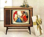
- RCA bewirbt seinen neuen Farb- fernseher zu Weihnachten 1957

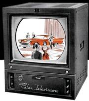
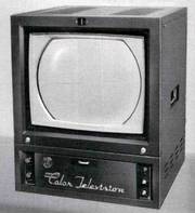
Vor der Entscheidung der FCC (etwa 1954), welches von mehreren propagierten Farbfernsehsystemen in den USA landesweit eingesetzt bzw. gesendet werden solle (und auch darf), gab es schon Farbfernseher verschiedenster Bauart. Bei den Amerikanern war eines wichtig, "möglichst bunt"sollte es sein. Als ich mit meinen Gastgebern 1986 durch Florida und insbesondere von Miami Süd die lange Straße zu "den Keys" (das ist die Südspitze von Florida) gefahren war, fiel mir auf, die kleinen Häuser waren mit den urkomischsten grellen und teils häßlichen übertriebenen Farben "angepinscht". Dort hatte ich drastisch gelernt, über Geschmack läßt sich trefflich streiten.
Schaun wir uns hier die Farbfotos der Farb-Scenen aus den ersten Farbfernsehstudios an, ist auch alles grell übertrieben. Wichtig waren eigentlich nur die Werbe-Spots und "Filmchen" - sie nennen das "commercials", bei denen das beworbene Produkt aus dem gesamten Bild herausstechen mußte, weiter nichts. Das teilweise übertriebene Qualtätsdenken der deutschen Entwickler und Ingenieure kam bei den Amerikanern erst viel später.
.
THE RCA TM-21 COLOR MONITOR
- Der erste amerikanische wirklich professionelle Monitor von RCA

by E. E. GLOYSTEIN and N. P. KELLAWAY - RCA Terminal Equipment Engineering *1)
*1) Development of the TM-21 was accomplished by an RCA engineering team. In addition to the authors, major contributions were made by L. J. Baun, R. A. Dischert. A. C. Luther. F. L. Benchly, R. J. Marian, C. R. Morris and R. H. Schirmer.
Wie fast alles in USA "state of the art"
The "state of the art" in compatible color television has been advanced by the introduction of the RCA TM-21 Color Monitor. This newly designed color display device is capable of producing high-quality pictures, stable enough to hold adjustments over long periods of time, and rugged enough to stand up under rigorous operating conditions.
- Anmerkung : Die Betonung liegt hier auf dem Wort "compatible". RCA hatte bereits sehr früh eine eigene Farbfernseh-Entwicklung und den richtigen Riecher gehabt, nämlich recht bald gemerkt, daß die FCC die "compatible" Farbfernsehvariante für zukunftsweisend betrachtete und vermutlich sich auch für diese RCA Entwicklung entscheiden würde. Das (closed circuit) Farbsignal im Fernseh-Studio war damals bereits weitgehend "normalisiert" (= als Standard festgelegt), sodaß bei diesem Kontroll-Monitor nur das NTSC-Empfangsteil ein neues Zusatzmodul war.
The TM-21 has been designed "from the ground up" to meet the requirements of broadcast stations and closed-circuit color television plants. It is expected to find many applications as an adjunct to color camera chains, as a general-purpose monitoring instrument, and as a high-quality display device in "prestige" applications, such as clients' booths and reception rooms.
.
Stable Design - Enhances Monitoring Applications
One of the most important applications for a color monitor is in control rooms where operators face the problems of setting up and matching color cameras.
Thanks to its high quality and stability, the TM-21 is unusually well qualified for this service. Compared to other monitoring devices the TM-21 offers the following benefits:
.
- (1) It provides a better check of registration during actual programming than the black-and-white master monitor.
- (2) Because of its own excellent deflection linearity (within 1% in both directions), a good check of camera deflection linearity is possible.
- (3) Provision for underscanning, to show the corners of the picture, permits better checking of camera framing, camera lens aberrations, and camera deflection transients. Underscanning also makes cue marks in the picture corners readily visible.
- (4) A highly stabilized method of black-level setting permits better evaluation of camera shading characteristics and clearly indicates the effects of camera pedestal adjustments.
- (5) Precision decoder circuits and highly linear output amplifiers produce a picture of improved color fidelity, so that camera color fidelity can be more accurately evaluated.
- (6) The improved picture sharpness facilitates checking of camera focus.
- (7) Ease of set-up and circuit stability reduce operating cost, because very little operator time is required to keep the monitor operating.
- (8) Excellent accessibility for servicing reduces both the maintenance cost and down-time in the event of tube or component failures.
.
master control or transmitter monitoring
Another important application for the TM-21 is at master control or transmitter monitoring points where the color picture must serve as final indication of the quality of signals being received or transmitted.
In this application, the stability of the monitor is particularly significant, because it is important that operators be certain whether observed picture faults are due to the monitor or to the signal itself.
When master control or transmitter operators are given a monitor in which they have confidence, they can do a much better job of taking or recommending corrective action when substandard signal conditions are detected.
.
Most color displays deliver about 275 lines
- Hier sticht vor allem diese (immer noch) runde Bildröhre ins Blickfeld. RCA hatte eine eigene Bildröhrenfertigung mit angeblich 800 Stück pro Tag.

In general-purpose monitoring applications, the provision for automatically removing the subcarrier trap in the monochrome channel when a monochrome picture is displayed is of special significance.
Most compatible color displays are limited in horizontal resolution to about 275 lines because of the necessity for attenuating the color subcarrier at 3.58 megacycles before it reaches the "kinescope".
- Anmerkung : Ganz deutlich zu erkennen ist, die amerikanische "kinescope" Bildröhre war 1958 immer noch kreisrund.
This limitation is not serious when the monitor or receiver is producing a color picture, because the addition of color more than compensates lor the loss in resolution.
When producing monochrome pictures, however, a 275-line limit is quite obvious in comparison with wide-band monochrome displays.
The TM-21 has avoided this limitation through its cross connection of the subcarrier trap with the color killer: hence, monochrome pictures are displayed with the full resolution capabilities of the color kinescope, about 450 lines.
- Anmerkung : Hier ist es wieder ganz deutlich, der Unterschied der NTSC Zeilenzahl und der am Ende dargestellten Linien. In USA waren sogar Fachleute verwirrt, welche Zahl denn nun ausschlaggebend ist (oder sei) für die Qualität des Fernseh-Bildes.
.
The TM-21 will do a very satisfactory job of displaying both color and monochrome pictures in many situations where it has heretofore been necessary to provide both a monochrome and a color monitor.
.
Important for "prestige" situations
Another application for the TM-21 is in "prestige" situations where it is important that pictures of the highest possible
quality be presented.
Both the professional appearance of the monitor and its excellent picture are definite assets in such places as clients' booths and reception rooms where the best possible impression on customers or on the public is desired.
Stability is important in these situations, too, because the monitor must often operate for long periods with no operator attention.
.
Serves as System Standard
The TM-21 is the first instrument designed to serve both as a color picture display device and as a piece of test equipment. With respect to circuit design, most previous color monitors have been approximately equivalent to color receivers with the tuner, intermediate- frequency amplifier, and sound sections removed.
Most of these devices have been designed with mechanical packaging making them suitable for use in broadcast plants, and have proved generally useful for color display purposes. These previous monitors have not been particularly useful as "standards of reference," however, because they have lacked the stability to suit them for this service.
In the TM-21, great pains have been taken to overcome the limitations of conventional receiver designs in order to produce pictures which are limited only by transmission standards, and capabilities of the color kinescope. Stability has been provided by extensive use of feedback and other stabilization techniques, and the mechanical design represents a new high in operating convenience and serviceability.
.
The Importance of Stability - Basics - Grundlagen

Before reviewing in some detail the design highlights of the TM-21, it is appropriate to comment briefly on the significance of stability in color monitors.
It is not enough to make a color monitor merely capable of producing a high-quality color picture - it must be capable of maintaining such a picture over long operating periods without frequent readjustments to compensate for circuit drifts.
While great progress has been made in reducing color television to a science, there is still enough "art" mixed in with the science to make it necessary that many adjustments in cameras and transmitting apparatus be made on the basis of what they do to the color picture.
Unless the operators who make such adjustments are provided with a highly stable color monitor, they can never be quite sure whether some of the effects they see in the monitor picture result from the signal or the display device (monitor).
Of course, stability in an electronic device doesn't just happen - it is a result of careful design. In the TM-21, for example, a high degree of stability has been achieved by the combination of three design approaches:
.
- (a) simplification of the basic circuit configuration to reduce to a minimum the possible sources of drift,
- (b) frequent use of inverse feedback, and
- (c) generous reserve factors in cases where feedback is not practical.
.
Circuitry is Designed About Five Main Chassis
To "set the stage" for detailed discussions of some of the unusual and significant characteristics of the TM-21, let us examine quickly some of the more obvious aspects of the monitor.
The front-view, Fig. 1. shows that the monitor has a professional appearance with an over-all size determined primarily by the 21-inch color kinescope.
- Anmerkung : "kinescope" ist die runde Bildröhre aus den USA von 1958, die bei uns keinen Anklang gefunden hätte. Bei der runden Front geht viel zu viel Fläche verloren. Offensichtlich hatten die Ingenieure das mit der Ablenkeinheit und deren Ansteuerung noch nicht im Griff. Im Philips Labor bei Valvo hatte man bereits ein rechteckiges Farbmuster am Laufen.
Cabinet dimensions are 27 inches wide, 33 inches high, and 28 inches deep. The only operating controls normally exposed are: brightness, contrast, and the power off-on switch. The main power fuses are also accessible on the front panel.
Internally the monitor consists of five main chassis mounted on a sturdy frame: (1) decoder, (2) output amplifiers, (3) deflection and high voltage, (4) convergence, and (5) power supply. The relationship between these chassis is shown in Fig. 2.
.
The functions of the five chassis
The functions of the five chassis are described briefly as follows:
.
- (1) The decoder processes the composite color signal to derive red, green, and blue signals suitable for controlling the color kinescope. It also contains a sync separator and a sync interlock circuit which permits optional use of external synchronizing pulses.
- (2) The output amplifiers increase the amplitudes of the signals from the decoder to the levels needed to drive the electron guns of the kinescope. They also provide for the restoration of the DC components of the signals.
- (3) The deflection and high-voltage chassis is controlled by composite sync from the decoder chassis. It provides sawtooth currents for the deflection yoke of the color kinescope, plus a source of regulated power at 25 kilovolts for the kinescope ultor. The protection circuits, which prevent kinescope damage from certain types of failure or improper operation, are located within this unit.
- (4) The convergence chassis develops second-order deflection currents, which are applied to the convergence yoke on the color kinescope for the purpose of adjusting the shapes of the red, green, and blue rasters so that they may be properly registered in all parts of the picture.
- (5) The power supply provides regulated +B power for the other chassis.
.
Mechanical Design Features Ready Access to All Components
Figure 3 shows how excellent serviceability is achieved by mounting the four mains chassis vertically with the tubes projecting inward. This design makes it possible to replace any tube from the top or rear of the monitor. Ready access to all small components and wiring is gained by simply removing Ihe side covers.
The same design configuration also provides good separation of heat sources from temperature-sensitive components, so that adequate cooling is possible with natural convection currents.
The mounting frame, made of sturdy aluminum angles, is constructed so that the monitor may be placed on any of its six surfaces without damage. However, it is unnecessary to gain access to the bottom of the monitor for any normal service functions.
As shown in Fig. 3, the deflection and high-voltage chassis is mounted at the lower left, with the power supply immediately above it. The decoder is at the lower right, mounted below the output amplifiers.
The convergence chassis, not shown in Fig. 3, is mounted as a subassembly just behind the middle portion of the front panel. This chassis, which contains only passive components, can be withdrawn from the front for servicing, see Fig. 4.
.
The mounting of the kinescope

Another outstanding feature of TM-21's mechanical design is the arrangement for mounting the kinescope. The decorative bezel surrounding the picture area may be readily removed to provide convenient access to a group of screw-driver slots in the periphery of the mask assembly, (see Fig. 5).
These screw-driver adjustments control the equalizing magnets which assure uniformity of color rendition in all areas of the screen. With the bezel removed, the safety glass is easily taken out so the kinescope faceplate can be cleaned. A front-panel, high-voltage interlock protects the operator during this procedure.
The metal cone of the kinescope is enclosed by a polyethylene boot, which serves as a high-voltage insulator, as a filter capacitor for the high-voltage power supply (since a conductive coating on the outside of the boot is grounded) and as a mechanical support which is clamped against the front panel. The upper section of the front panel is hinged at the bottom, so that it can be dropped forward to permit convenient replacement of the kinescope as illustrated in Fig. 6.
.
Decoder Chassis Differs Significantly From Receiver Design
The area in which the monitor differs most significantly from conventional receiver designs is the decoder. The block diagram of this chassis is shown in Fig. 7; a photograph in Fig. 8.
Many of the drift problems in conventional receiver or monitor designs fall in this section, because it is necessary that separate but parallel signal channels be used for many of the processing functions.
For example, in a receiver the high-frequency portion of the signal must be processed in channels containing demodulators and filters, while the low-frequency portion is passed through delay equalizing networks and an aperture compensator.
Drift problems can arise unless such separate but parallel stages are highly stabilized with respect to both gain and phase characteristics. In the TM-21 decoder, the drift problem has been kept under control by reducing the number of stages required in the parallel paths, by eliminating the need for gain in these paths, and by stabilizing each of the individual stages.
Video Driver Handles All Signal Components Simultaneously
The heart of the decoder design is a stabilized "video driver" stage which drives the monochrome channel and the burst-controlled oscillator from its plate circuit, and the two chrominance demodulators from its cathode.
The DC component is restored at this stage by means of a feedback-stabilized clamp. One of the gating stages involved in this feedback clamp has been made to serve as a burst separator as well, thus eliminating a separate tube for this function.
In the video driver the plate signal current is inherently equal to the cathode signal current to eliminate the possibility of gain variations in the plate circuit relative to the cathode circuit.
Prior to the video driver stage, the input signal is raised to a relatively high level (about 12 volts, peak-to-peak) by an amplifier equipped with a nonselective or wide-band gain control.
By using this high level at the driver stage virtually all of the voltage gain required in the entire decoder is supplied by an amplifier which handles all signal components simultaneously.
This technique eliminates the problem of matching the gains of several individual amplifiers. In the stages which follow the video driver, (which must necessarily be split into separate channels), it is possible to sacrifice voltage gain for the sake of stability and still deliver signals at about a 1-volt level at the output of the decoder.
The amount of degeneration (or feedback) that it has been possible to incorporate in the TM-21 by following this approach has made practical the elimination of several conventional gain controls (normally provided in decoders to compensate for circuit variations).
.
Burst Controlled Oscillator Features Single Output
One of the channels following the video driver stage is the burst-controlled oscillator, consisting of a crystal-controlled 3.58 mc oscillator shunted by a reactance tube whose control voltage is derived from a phase detector.
This detector compares the oscillator output with the separated bursts provided by the video driver. Special attention has been given to drift problems in this oscillator, so that the phase of its output remains stable relative to the phase of the chrominance signal delivered from the cathode side of the video driver.
In conventional decoder designs, the burst-controlled oscillator normally delivers two subcarrier outputs, (90 degrees apart in phase), to the chrominance demodulators. A popular method of deriving the two outputs is to use a pair of tuned circuits, one tuned above resonance and the other below resonance to achieve the required 90 degree phase shift.
In the TM-21 decoder, however, a potential phase stability problem has been avoided by providing only a single output from the oscillator. This output is tied directly to both demodulators, so that there can be no relative phase drift between them.
The required 90 degree phase shift is provided in the video channel by passing the input signal to the I demodulator (was ist das ???) through a precision delay line equivalent to 90 degrees at 3.58 megacycles. The delay line is manufactured with a tolerance of only ±1 degree; hence it is possible to eliminate the conventional 90 degree or quadrature phase control.
The presence of the delay line in the I video channel (was ist das ???) poses no problem, because it is very simple to take it into account when adjusting the total delay of the I channel relative to the narrowband Q channel.
Stabilized Diode Demodulators Eliminate Drift
The demodulators themselves are a stabilized diode type, as shown by the simplified schematic, Fig. 9. In essence, the circuit is a fast-acting clamp. The diodes are closed periodically at a 3.58 MC rate, and their effect on the signal is to connect the output side of the 120 mmf capacitor to ground through the center tap of the 3.58 MC transformer.
The charge stored in the 0.01 mf capacitor through the rectifying action of the diodes serves to make the diodes conductive only during the extreme peaks of the subcarrier cycle. Because the clamp is closed only momentarily, the output side of the 120 mmf capacitor is normally free to follow the variations in the input signal.
The average output level, however, is a function of the input level at the instants when the diode conduction occurs, as illustrated by the waveform sketches in Fig. 10. This average level is affected by both the amplitude and the phase of the incoming chrominance signal, and represents the desired demodulated signal.
The major advantages of this demodulator circuit are: (1) it has no video gain drift problem, since it behaves in principle like a fast-acting switch, (2) it is insensitive to the level of the CW subcarrier signal, provided the CW signal is always of higher amplitude than the modulated RF signal.
.
High Resolution Pictures From Monochrome Channel
There are several unusual features in the monochrome channel of the decoder, driven from the plate side of the video driver. A clipper in the plate circuit removes both the sync and burst components of the input signal.
In the blanking interval thus cleared, there is provision for adding a "brightness control pulse" of adjustable amplitude. This pulse is derived from separated sync and makes possible a considerable simplification in the adjustment of the monitor for proper gray scale balance.
Since the pulse is introduced in the monochrome channel ahead of the matrix-ing operation, it is automatically supplied in the proper proportions to the red, green, and blue channels which are separated at the output of the matrix. As will be explained in more detail later, the brightness pulse serves as a reference level to which the signals are clamped in the DC restoration process at the kinescope guns.
.
Attenuation in the monochrome channel
In all compatible color display devices it is necessary to provide attenuation in the monochrome channel to prevent the subcarrier components of the signal from reaching the kinescope by this path.
In the TM-21, this need is met by a simple trap circuit. When the monitor is operated from a monochrome signal (i.e., one without color sync bursts), the "color killer" not only disables the chrominance channels to avoid crosstalk effects, but also removes the trap from the monochrome channel permitting substantially higher resolution. This feature is of considerable value in situations where the monitor is used for viewing both monochrome and color pictures.
A delay line is needed in the monochrome channel to compensate for the greater delay of the I and Q channels (wo wird das erklärt ???) . Following this delay line, an aperture compensator of a linear-phase-shift type provides an adjustable boost for the higher frequency components of the signal to compensate for the finite spot size of the kinescope beams.
The aperture compensator is also tied to the color killer through a relay, so that the shape of the high-boost response curve is altered automatically when the monitor is operated from monochrome signals. This automatic shift in aperture compensation further enhances the sharpness of monochrome pictures.
.
Gain Controls Eliminated in Matrix Section
In the matrix section of the decoder, the M, I, and Q signal components are cross-mixed in the proper proportions to
form red, green, and blue signals.
The matrix circuit used in the TM-21 is of a new design, requiring only one phase inverter, which is highly stabilized by degeneration.
The relative gains of M, I, and Q signals entering the matrix are so thoroughly stabilized that no gain controls are required. To provide for situations where it is desired to use the monitor with a substandard signal having improper amplitude of the chrominance signal relative to the monochrome signal, a "chroma" or saturation control of limited range is provided in the form of a frequency-response trimmer on the input amplifier.
In the normal operating condition, (selected by a front-panel set-up switch, to be described later), this chroma control is disabled, and the monitor display may be accepted as a good indication of the actual quality of the signal applied to its input.
Gain controls external to the matrix are used for adjusting the amplitudes of the green and blue signals relative to the red.
These controls are needed to compensate for component differences in the subsequent output amplifiers and for differences in the relative efficiencies of the three phosphors.
.
The sync separator
The decoder chassis also contains the sync separator, which provides pulses for controlling the deflection circuits as well as some of the keying functions in the decoder.
There is an optional input for external sync for use in situations where the monitor is operated from noncomposite signals. An interlock circuit permits remote selection of internal or external sync in applications where both composite and noncomposite signals are encountered.
Output Amplifiers Feature Excellent Amplitude Linearity, Frequency Response and Gain Stability
The amplifiers which raise the decoder output signals to the levels necessary to operate the color kinescope are mounted on the chassis shown in Fig. 11. In order to maintain the proportionality of the red, green, and blue signals necessary for good color fidelity, the individual amplifiers must have excellent amplitude linearity, frequency response, and gain stability.
The operation of one of the three nominally identical channels on the output amplifier chassis is illustrated in Fig. 12. A current feedback loop from the output stage to the input stage accomplishes the following:
(1) The gain is stabilized against line voltage variations, tube aging, and especially, loss in transconductance in the output stage.
(2) Excellent amplitude linearity is maintained (less than 1 per cent differential gain for an 80 volt white picture).
(3) Uniform frequency response, in excess of 6 megacycles, is maintained up to the output tube plate circuit. The passive circuitry, which direct-couples each output stage to its respective kinescope cathode, is a series-shunt compensated network that maintains uniform response to about 5.5 MC.
.
No signal = 20% maximum luminance with gray screen
Instead of conventional diode-type DC restorers, the TM-21 employs gated damps around the final amplifier stages. The three individual clamps are operated from a single reference voltage in such a way that the DC plate voltages for the three output amplifiers are identical. The different grid bias conditions required to maintain this condition are automatically established by the clamp circuits, which sample the outputs at the plates but apply their correction voltages to the grids.
The gated DC restorers are normally operated by separated sync pulses, so that the clamping occurs during the transmission of the special brightness pulse inserted by the decoder. In the event that the sync pulses to the monitor are interrupted, con-
trol of the clamping operation is automatically taken over by horizontal pulses derived from the deflection chassis. This prevents prolonged operation under improper bias conditions. When the monitor is operated under no-signal conditions, the brightness pulse is absent, but the monitor operates safely with a gray screen of about 20% maximum luminance.
.
Deflection Circuits are Feedback Stabilized
While the deflection circuits (Ablenk-Verstärker) in the TM-21 are based on conventional principles, they include a number of design refinements that are worth pointing out. The circuits are mounted on the chassis, shown in Fig. 13, and their operation is illustrated by the block diagram, Fig. 14.
The vertical deflection circuit is stabilized by a feedback connection between the output stage and the sawtooth generator. This arrangement not only makes the circuit highly immune to variations in supply voltages and tube characteristics, but also permits the vertical size (or height) to be adjusted over wide limits without disturbing the scanning linearity.
The horizontal deflection oscillator and sawtooth generator is a refined version of the conventional synchroguide circuit, offering a good combination of stability, noise immunity, and optimum phasing of the horizontal retrace period.
Added stability is provided by "beefing up" the horizontal output circuit to provide generous reserve factors. While typical receiver designs use a single horizontal output tube to deflect the 21-inch color kinescope, the TM-21 employs a pair of 6CD6-GA's in parallel to perform this function, and a pair of 6AU4GTA's to serve as dampers.
An unusual type of bifilar winding is used in both the horizontal and vertical output transformers to facilitate the introduction of centering current without requiring bulky isolation chokes around the centering potentiometers.
.
Hier etwas Besonderes - die Vollbildanzeige
A unique and significant feature of the TM-21 deflection chassis is the provision of an operational "size" switch for switching rapidly from a normal rounded-side picture to a reduced-sized picture that permits observation of the corners. This switch operates on both the horizontal and vertical circuits simultaneously.
- Anmerkung : Wie man auf allen Fotos aus dieser Zeit zwischen 1955 und 1960 unschwer erkennen kann, war die runde Farb-Bildröhre das schwächste Teil des ganzen amerikanischen Farbzaubers. Das von der Kamera gelieferte Bild wurde erheblich beschnitten, um überhaupt Details erkennen zu können. Mit einem Schalter konnte man an diesem Monitor das Bild so weit verkleinern, daß es gänzlich auf der Röhre zu sehen war, nur eben erheblich geschrumpft.
.
High Voltage Chassis Includes Protection Circuits
The high voltage supply for the "kinescope ultor" is of the conventional "kickback" type, conservatively designed to deliver all the high-voltage power that the kinescope can safely utilize (1.25 ma at 25 kv = 1,25 Milli-Amere bei 25.000 Volt). A pair of shunt regulator tubes maintain good regulation under all operating conditions.
Because of the reserve power and signal voltages available to operate the color kinescope near the upper limits of its performance capabilities, special attention has been given to the design of protection circuits to guard against damage to the kinescope in the event of certain failures or improper operating conditions.
If the beam current becomes excessive, resulting from improper operating voltages or excessive, video drive, the bias on the kinescope grids is automatically shifted to a safe value to prevent damage to the shadow mask.
In the event of horizontal deflection failure, extreme overdrive, or a short-circuit in the high voltage system, the protection circuit not only cuts off the kinescope guns but also disconnects the main +B supply on the power supply chassis. The protection circuit itself is designed to be "fail safe," so that failure in any of its components will turn the monitor off.
.
Convergence Circuits Designed for Easy Set-Up

The convergence chassis, shown previously in Fig. 4, contains purely passive circuits for modifying certain waveforms derived from the deflection chassis before applying them to the convergence yoke surrounding the kinescope gun structures.
The word "convergence," as applied to color-display devices, refers to the process of adjusting the positions of the red,
green, and blue beams so that the respective images are registered in all parts of the screen.
Because the effective distance between the guns and the screen assembly varies with the deflection angle, it is necessary to control the convergence with dynamic waveforms containing both horizontal-frequency and vertical-frequency components.
The basic waveforms consist of a parabola and a sawtooth at each frequency, but these must be mixed in different proportions for each gun.
In the TM-21, unusually good performance with respect to convergence is made possible by the conservative design of the deflection circuits, which provide good waveforms to start with.
.
16 Justage-Potentiometer für die Convergenz der Farbe
As indicated in Fig. 14, both the output tubes and the output transformers serve as signal sources for the convergence circuits. Stability and ease of operation were given strong emphasis in the design of the convergence section of the TM-21.
An examination of the convergence control panel, shown in Fig. 15, will show how the operation of this section of the monitor has been greatly simplified.
Two features of the convergence circuit design which particularly facilitate a straightforward set-up procedure are:
- (1) the controls are arranged so that the red and green rasters may be adjusted as a pair, relative to each other, after which the blue raster may be brought into registration relative to the red-green pair, and
- (2) every control has been made to direct some type of movement in either the horizontal or vertical direction, not along the 120-degrees axes that prove to be quite confusing in conventional convergence arrangements.
The large number of convergence controls needed for a tricolor tube (16 in the case of the TM-21) need not seem too formidable if each one performs some readily-understood function.
Those used in the TM-21 are so designated and arranged on the control panel that it is easy to visualize them as trimming adjustments for the deflection circuits. There are only five basic types of controls (see Fig. 15) and these are readily understood.
.
Details vom Bedienteil
The position controls are only trim adjustments for the centering function, while size and linearity carry the same connotation as in conventional deflection systems. The tilt and bow controls produce these effects on the lines of the grating pattern commonly used to facilitate convergence adjustments. The bow control affects the curvature of the lines, while the tilt controls are used to make them parallel.
Note that the controls are logically grouped in two ways. The vertical, static, and horizontal adjustments are located in separate columns. The upper controls in each column adjust the red and green rasters relative to each other, while the lower controls adjust the blue raster relative to the red-green pair.
A screen selector switch just to the left of the convergence control panel makes it possible to view any of the rasters separately, or to view only the red-green pair.
.
Three-in-One Regulated Power Supply
The power supply for a piece of electronic equipment is often taken for granted as a circuit of obvious function and little significance. In the case of the TM-21, however, the power supply plays a vital role in helping the other sections of the monitor do their jobs properly.
The purpose of a regulated supply is to eliminate the interactions and cross-coupling between circuits that occur if supplies of appreciable source impedance are used. Also, the stabilization of the output voltages against line voltage changes preserves the performance designed into the other circuits.
The block diagram, Fig. 16, indicates that the TM-21 supply is actually three power supplies in one. It provides the optimum regulated voltage for each section:
- +400 volts for the deflection circuits,
- +200 volts for the video output amplifiers, and
- +280 volts for most of the other circuits.
Since the load requirements were definitely known in each case, an optimum degree of regulation is incorporated without costly over design. As shown in Fig. 16, a common transformer serves all three supplies, but they have separate rectifiers and series regulators.
All three are tied to a common voltage-reference system, so that calibrating the +200 volt section automatically sets the others to their proper values. The use of precision resistors in this common voltage reference system eliminates the need for several controls that would otherwise be required.
The use of cool and efficient germanium rectifiers makes it desirable to delay the application of plate voltage to the series regulator tubes until their heaters have had an opportunity to reach the proper operating temperature.
The main power transformer is energized through a relay which is controlled by an amplifier deriving its power from a small auxiliary transformer and a vacuum-tube rectifier.
Delay is provided by the warm-up cycles of the auxiliary rectifier and the amplifier itself. Time constants give the proper delay when the the monitor is turned off and on again quickly. The same auxiliary power source also supplies current to the protection circuit in the deflection unit.
The protection control voltage also operates through the
same relay as the time delay amplifier to disconnect the power supply automatically in the event of a failure in the horizontal deflection or high-voltage circuits.
The power supply is mounted on a separate chassis, similar in mechanical design to those used for the other sections of the monitor, see Fig. 19. Note that a number of fuses are provided to protect individual sections of the circuit. All fuse-holders are of an indicating type, so it is easy to determine which fuse has blown in the event of trouble.
.
Rapid Set-Up Procedure
Strictly speaking, a television monitor should not require "operation" because its function in a television system is to serve as a tool for an operator.
His (the operators) main job is to operate a camera, to check the quality of signals, or to select the proper signals for a television program. On the block diagram of a complete television system, the monitors are properly shown as appendages, not as main links in the equipment chains.
It is desirable, therefore, to make a monitor so stable that its operation may be taken for granted throughout most of the working day, leaving the operators free to concentrate on their major functions.
Such stability has been achieved in the TM-21, so its "operating" controls are more properly called "set-up" controls. Even though the set-up procedure need not be carried out very often, no effort has been spared to make the procedure as rapid and straightforward as possible.
All of the controls needed for routine set-up of the TM-21 are mounted on the front panel, which is logically divided into three sections. The center section contains the convergence controls, which were discussed previously. The right-hand side of the panel (see Fig. 18) contains the deflection controls, whose functions are made obvious by clear labeling.
Note that the FOCUS control is included in this section of the control panel, along with an A-C RESET button which restores the monitor to normal operation when the protection circuit trips it off. The SIZE switch is mounted directly under the FOCUS control.
The left-hand section of the control panel, shown in Fig. 18, contains the controls for adjusting the decoder and for setting up the kinescope for proper color balance. It is in this section of the panel that the TM-21 differs most radically from conventional color monitor or receiver designs. Not only are there fewer controls to contend with, but also the controls are designed to facilitate an unusually straightforward set-up procedure, requiring no external test apparatus other than a source of standard color-bar signals. While some of the controls shown in Fig. 18 are quite obvious, it may be helpful to describe briefly what they do in terms of the circuits they actually control.
.
The BRIGHTNESS control
The BRIGHTNESS control produces the same effect as conventional brightness controls, even though it operates in an unusual manner. Instead of varying the bias on the kinescope, it varies the level of a special pulse added to the signal in
place of the normal sync and burst signals, see Fig. 19.
This technique is made feasible by the use of keyed clamps in the output amplifiers, which operate during the time interval of the added pulses. The virtue of this brightness control technique is that it eliminates the need for individual red, green, and blue background controls.
The single BRIGHTNESS knob automatically exercises the proper degree of control over the three color channels because the added pulse is passed through the standard decoder matrix.
.
The CONTRAST control and SYNC SELECTOR usw.
The CONTRAST control varies gain of input stage in the decoder (see Fig. 7), and varies the monochrome and chrominance components of the picture equally.
The SYNC SELECTOR enables the operator to switch conveniently between external sync and the internal sync pulses separated from the composite video signal.
In the REMOTE position, this switch brings the sync interlock into operation, so that the use of internal or external sync is controlled from a remote point (such as a switcher) through a DC control lead.
The APERTURE COMPENSATOR adjusts the degree of high-peaking in the monochrome channel for optimum picture sharpness without objectionable overshoots.
The TEST switch is the key to the simplified set-up procedure for the TM-21. By moving this switch through its several positions and making specific adjustments at each step, the monitor can be brought into proper operating condition with a minimum of effort. Now, let us go through each of these steps rapidly following the diagrams on the facing page.
In the first position, the signal is automatically disconnected, but a fixed brightness pulse remains. In this position, the RED SCREEN control is adjusted for cut-off. (See Fig. 20A.)
(Weitere 2 Seiten skipped - zu viel Text)
.
Conclusion
.
Design and production of this new 21-inch Color Monitor, Type TM-21 represents a significant advance in the "state of the art" in color television. Its test equipment design allows it to be used as a new "standard of reference" for color systems.
Color telecasters everywhere will find many applications for this new monitor as a general purpose color monitoring instrument, as an adjunct to color camera chains, and as a high quality display device in clients' and reception rooms.
.
Bildunterschriften
FIG. 1. New RCA TM-21 Color Control Monitor. Only operating controls normally exposed are brightness, contrast and ON-OFF switch.
FIG. 2. Over-all block diagram, showing Ihe five major chassis in the TM-21.
FIG. 3. Rear-quarter view oi TM-21 with side and top covers removed, showing how the chassis are mounted within the main frame.
FIG. 4. Front view of the TM.21. with the convergence chassis withdrawn for easy servicing. Contained in cover is detailed procedure for kinescope set-up. including convergence.
FIG. 5. Decorative bezel surrounding picture area is removed for access to the equalizing magnets and safety glass.
FIG. 6. Monitor front panel is readily swung down for quick removal of kinescope.
FIG. 8. Decoder circuits are housed on a single chassis.
FIG. 12. Simplified block diagram of one output amplifier channel.
FIG. 13. Deflection and high-voltage chassis.
FIG. 14. Block diagram of deflection, high volt. age. and protection circuits.
FIG. 15. Convergence control panel.
FIG. 17. Three-in-one power supply chassis.
FIG. 18. Close.up of control section. Located left to right are decoder, convergence and deflection control panels.
FIG. 19. Waveform sketches illustrating the operation of the BRIGHTNESS control.